Appendix D (for reference) Examples of diagrams and markings of elements of metal structures. Appendix D (for reference) Examples of diagrams and markings of elements of metal structures Support forces in the list of elements
Crap. 8

Crap. 9
3.3.14. It is permissible not to make drawings for simple parts directly included in the monolithic reinforced concrete structure, but to provide all the necessary data for their manufacture in the specifications and, if necessary, place images of these parts on the drawing of the monolithic structure. At large quantities parts, the data necessary for their manufacture is given in a statement in form 6.
An example of filling out the statement is given in Appendix 11.

3.4. Specifications for layout diagrams of structural elements
3.4.1. The specification for the layout of structural elements is drawn up in form 7 or 8 of Appendix 7 of GOST 21.101.
3.4.2. The specification for the layout of prefabricated structures is filled out in sections:
1) elements of prefabricated structures;
2) monolithic areas;
3) steel and other products.
3.4.3. The specification of a monolithic structure consisting of several elements, each of which is subject to a separate reinforcement scheme, is compiled in sections for each element.
3.4.4. The name of each section of the monolithic structure specification is indicated as a heading in the “Name” column and underlined. The section names include the brand of the element and, separated by a dash, the number of elements per monolithic structure.
Examples: 1. Beams Bm1 - pcs. 2.
2. Plate PM1 - pcs. 1.
Each section of the monolithic structure specification consists of subsections, which are arranged in the following sequence:
1. Assembly units.
2. Details.
3. Standard products.
4. Materials.
In the “Assembly units” section, write down the elements directly included in the specified monolithic structure in the following sequence:
1. Spatial frames.
2. The frames are flat.
4. Embedded products.
The subsection “Materials” records materials directly included in the specified structure (for example, concrete).
4. WORKING DOCUMENTATION
FOR CONSTRUCTION PRODUCTS
4.1. The working documentation for a construction product generally includes a specification, an assembly drawing, drawings of parts and, if necessary, technical specifications.
4.2. When executing a group working document for products, products of the same name, uniform configuration and having common design features are combined into one group.
4.3. Variable sizes, not the same for all designs, covered by one image, are marked with letter designations, the number of which should, as a rule, be no more than three.
4.4. If necessary, the product drawings include a test diagram, design diagram, or indicate their load-bearing capacity.
4.5. The assembly drawing of the product or its schematic representation indicate the attachment points for lifting or supporting devices in accordance with the drawing. 10 .

INTERSTATE COUNCIL FOR STANDARDIZATION, METROLOGY AND CERTIFICATION
INTERSTATE COUNCIL FOR STANDARDIZATION, METROLOGY AND CERTIFICATION
INTERSTATE
STANDARD
Official publication
SSH1LTTM1fP[M
GOST 21.502-2016
Preface
The goals, basic principles and basic procedure for carrying out work on interstate standardization are established by GOST 1.0-2015 “Interstate standardization system. Basic provisions" and GOST 1.2-2015 "Interstate standardization system. Interstate standards. rules and recommendations for interstate standardization. Rules for development, acceptance, updating and cancellation"
Standard information
1 DESIGNED Closed joint stock company“Central Order of the Red Banner of Labor Scientific Research and Design Institute of Building Metal Structures named after. N.P. Melnikov" (JSC "TsNIIPSK im. Melnikov")
2 INTRODUCED by the Technical Committee for Standardization TC 465 “Construction”
3 ADOPTED by the Interstate Council for Standardization, Metrology and Certification (protocol dated November 22, 2016 No. 93-P)
4 By order Federal agency on technical regulation and metrology dated December 2, 2016 No. 1917-st interstate standard GOST 21.502-2016 put into effect as a national standard Russian Federation from July 1, 2017
5 INSTEAD GOST 21.502-2007
Information about changes to this standard is published in the annual information index “National Standards”, and the text of changes and amendments is published in the monthly information index “National Standards”. In case of revision (replacement) or cancellation of this standard, the corresponding notice will be published in the monthly information index “National Standards”. Relevant information. notification and texts are also posted in information system common use- on the official website of the Federal Agency for Technical Regulation and Metrology on the Internet ()
© Stamdartinform. 2017
In the Russian Federation, this standard cannot be fully or partially reproduced, replicated and distributed as an official publication without permission from the Federal Agency for Technical Regulation and Metrology
GOST 21.502-2016
1 area of use............................................... ..................1
3 Terms and definitions................................................... .................2
4 General provisions....................................................................2
5 Composition of working documentation................................................... ............2
6 Rules for the design of drawings of the KM brand.................................................... ....3
6.1 General data on working drawings.................................................... .....3
6.2 General drawings metal structures......................................3
6.3 Layout diagrams of elements of metal structures....................................4
6.4 Drawings of elements of metal structures............................................4
6.5 Drawings of metal structures components....................................................5
7 Specifications of rolled metal.................................................... ..........5
Appendix A (mandatory) Symbols and designations of fasteners
and seams of welded joints.................................................... ..7
designs........................................................ .............9
Appendix B (for reference) Example of loads on foundations....................................11
Appendix D (for reference) Examples of general view drawings....................................12
Appendix E (for reference) Examples of diagrams of elements of metal structures____16
Appendix G (for reference) Example of filling out the list of elements....................................19
Appendix I (for reference) An example of a drawing of a metal structure element... ..20
Appendix K (for reference) Example of a drawing of a metal structure assembly.......21
Appendix M (for reference) Example of filling out a specification for rolled metal products...................23
GOST 21.502-2016
INTERSTATE STANDARD
System project documentation for construction
RULES FOR EXECUTION OF WORKING DOCUMENTATION FOR METAL STRUCTURES
System of design documents for construction. Execution rules of working documents for metal structures
Date of introduction - 2017-07-01
1 area of use
This standard establishes the composition and rules for the execution of working documentation for building metal structures, drawings of the KM brand.
The requirements of this standard do not apply to the execution of detail drawings of metal structures of the KMD brand.
2 Normative references
8 of this standard uses regulatory references to the following interstate standards:
GOST 2.306-68 one system design documentation. Designations of graphic materials and rules for their application in drawings
GOST 2.312-72 Unified system of design documentation. Conventional images and designations of seams of welded joints
GOST 2.31S-68 Unified system of design documentation. Simplified and conventional images of fasteners
GOST 2.321-84 Unified system of design documentation. Letter designations GOST 2.410-68 Unified system of design documentation. Rules for making drawings of metal structures
GOST 21.001-2013 System of design documentation for construction. General provisions GOST 21.101-97* System of design documentation for construction. Basic requirements for design and working documentation
GOST 21.201-2011 System of design documentation for construction. Conventional images of elements of buildings, structures and structures
GOST 21.501-2011 System of design documentation for construction. Rules for the execution of working documentation of architectural and structural solutions
GOST 535-2005 Long-rolled and shaped rolled products made of carbon steel of ordinary quality. General technical conditions
GOST 4121-96 Crane rails. Specifications
GOST 8240-97 Hot-rolled steel channels. Assortment
GOST 8509-93 Hot-rolled equal flange steel angles. Assortment
GOST 19903-74 Hot-rolled sheet products. Assortment
GOST 23118-2012 Steel building structures. General technical conditions
GOST 26020-83 Hot-rolled steel I-beams with parallel flange edges. Assortment
* GOST R 21.1101-2013 is in force on the territory of the Russian Federation.
Official publication
GOST 21.502-2016
GOST 26047-2016 Steel building structures. Symbols (brands)
GOST 27772-2015 Rolled products for construction steel structures. General technical conditions
Note - When using this standard, it is advisable to check the validity of the reference standards in the public information system - on the official website of the Federal Agency for Technical Regulation and Metrology on the Internet or using the annual information index “National Standards”, which was published as of January 1 of the current year, and on issues of the monthly information index “National Standards” for the current year. If the reference standard is replaced (changed), then when using this standard you should be guided by the replacing (changed) standard. If the reference standard is canceled without replacement, then the provision in which a reference is made to it is applied in the part that does not affect this reference.
3 Terms and definitions
This standard uses terms according to GOST 21.001, GOST 21.501. as well as the following term with the corresponding definition:
3.1 costructure unit(s): Interface, connection between elements of building structures and their components.
4 General provisions
4.1 Detailed documentation of metal structures is carried out in accordance with the requirements of GOST 21.101 (except for section 6) and this standard.
4.2 Conventional graphic images of elements of buildings, structures and building structures are accepted in accordance with GOST 21.201.
4.3 Symbols of rolled profiles are adopted in accordance with GOST 2.410.
4.4 Graphic images of materials in sections, sections, as well as the rules for their application are accepted in accordance with GOST 2.306.
4.5 Symbols (grades) of metal structures are accepted according to GOST 26047.
4.6 The main letter designations are adopted in accordance with GOST 2.321.
4.7 Images of fasteners in connections must correspond to those specified in GOST 2.315 and table A.1 (Appendix A).
4.8 Conventional images and designations of seams of welded joints must correspond to those specified in Table A.2 (Appendix A).
In this case, the designation of seams can be indicated without extension lines, placing them directly above or below the image of the corresponding weld, regardless of whether the weld is visible or invisible.
It is allowed to perform conventional images and designations of seams of welded joints in accordance with GOST 2.312.
5 Composition of working documentation
5.1 The working documentation of metal structures includes:
Working drawings (main set of working drawings of the KM brand);
Rolled metal specifications:
Calculations.
Note - Calculations are not included in the working documentation, unless otherwise specified in the agreement (contract) and design assignment.
5.2 The main set of working drawings of the KM brand includes:
* general data on working drawings;
General view drawings of metal structures of a building or structure (plans, sections);
> layout diagrams of elements of metal structures:
Lists of elements for layout diagrams of metal structures;
Drawings of elements of metal structures;
Drawings of components of metal structures.
GOST 21.502-2016
5.3 Working drawings of the KM grade must contain the necessary and sufficient data for the development of detail drawings of metal structures of the KMD grade. project for the production of works and the order of rolled metal and metal products.
Deviations from the working drawings of the KM brand are not allowed. If necessary, these deviations must be agreed upon with the organization that developed the working drawings of the KM brand.
6 Rules for the design of drawings of the KM brand
6.1 General information on working drawings
6.1.1 On the first sheets of the main set of working drawings of the KM brand, general data is given in accordance with GOST 21.101.
6.1.2 V general instructions in addition to the requirements provided for by GOST 21.101. lead:
Information about the main design features of a building or structure:
Information about loads and impacts on metal structures:
Design diagram of structures with necessary explanations:
Description of installation and factory connections:
Instructions for protecting metal building structures from corrosion in accordance with GOST 23118 and other regulatory documents:
Instructions for manufacturing and installation, including requirements for quality control of welded joints. and geometric accuracy sizes in accordance with current regulatory documents.
6.1.3 Information on loads and impacts on metal structures is usually given in tabular form, which indicates: standard and design values of loads, safety factors for loads and data on possible combinations of technological and other loads and impacts in accordance with the requirements of the current regulatory documents*, technological and architectural and construction specifications.
Examples of loads and impacts on metal structures are shown in Figures B.1 and B.2 (Appendix B).
6.1.4 Loads on foundations include:
Value of loads on foundations:
The accepted rule for signs of loads on foundations;
Layout diagrams of foundation bolts for each brand of foundation;
Diameters, heights of protruding parts, lengths of cuts, steel grades of foundation bolts, embedded parts;
Requirements for foundation deformability (if necessary).
An example of performing loads on foundations is shown in Figure B.1 (Appendix B).
6.2 General view drawings of metal structures
6.2.1 General drawings are made in the form of plans, views or sections of the corresponding structures with a simplified or schematic representation of the elements.
In drawings of the general view of metal structures of a building or structure, diagrams of structures with connections are given, indicating the relative position of the structures, their connections and support on the foundations.
6.2.2 On the general drawings the following is indicated:
Coordination axes of a building or structure;
Dimensions that determine the distances between the coordination axes, marks of areas located on different levels, other required sizes;
Binding to coordination axes buildings (structures) or, if necessary, other structures and the main parameters of technological equipment (handling and transport, etc.). affecting structures;
Overall and characteristic dimensions;
* In the Russian Federation, SP 20.13330.2011 “SNiP 2.01.07-85* is in force. Loads and impacts."
GOST 21.502-2016
Elevations:
Adjacent building construction, not developed in the working drawings of the KM brand. which are depicted schematically with thin lines:
Lines and designations of sections;
Designation of extension elements (nodes and fragments);
Brands of structural elements.
Overall dimensions are given both for the entire structure as a whole (spans, length, width, height, diameter, etc.), and for its largest elements (height of trusses, etc.).
Characteristic are the dimensions that determine the shape of a building or structure and its individual parts: slopes (roofs, bottoms, road surfaces, etc.), radii of curved surfaces, dimensions that determine the change in the width of the towers along the height, etc.
6.2.3 Examples of general drawings are shown in Figures G1-G.4 (Appendix D).
6.3 Layout of elements of metal structures
6.3.1 Layout diagrams of elements of metal structures are carried out in accordance with subsection 6.3 of GOST 21.501-2011, taking into account the specifics of the execution of drawings of metal structures.
6.3.2 Marking of elements of metal structures is usually indicated on the layout diagrams of elements. Structural elements not included in the layout diagrams of elements are marked on the general view drawings and assemblies in accordance with GOST 26047.
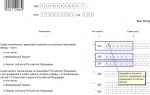
6.3.3 A list of elements is compiled for each layout of elements of metal structures according to form 1 given in Appendix E.
The list of elements is placed on a sheet containing the corresponding diagram.
It is allowed to list elements on a separate sheet.
It is allowed to draw up one general list of elements for all layout diagrams, indicating in the “Note” column a link to the sheets where these diagrams are located.
6.3.4 V technical requirements, placed on the layout diagrams of elements, give:
Force values for calculating the attachment of elements that are not indicated in the drawings and in the list of elements;
Additional information and technical requirements for manufacturing and installation that are not included in the general data.
6.3.5 Examples of the layout of elements of metal structures are shown in Figures D.1 and D.2 (Appendix D).
6.3.6 An example of filling out the list of elements is shown in Figure G.1 (Appendix G).
6.4 Drawings of elements of metal structures
6.4.1 If the layout of elements of metal structures is not sufficiently identified design features elements for the development of detail drawings of the KMD brand. then additionally, drawings of elements of metal structures are performed.
6.4.2 The drawings of elements of metal structures indicate:
Geometric dimensions;
Effort values;
Support reactions;
Markings of the top and bottom of structural elements;
Dimensions of individual parts:
Type of installation and factory connections;
Names or grades of metal of the parts included in the element;
Technical requirements.
6.4.3 The technical requirements on the drawings of elements of metal structures include:
Force values for calculating attachments not indicated on the drawing;
Additional requirements for the manufacture and installation of elements;
Numbers of sheets on which the layout diagrams of structural elements are located.
6.4.4 The dimensions of welds and the number of fasteners are determined when developing detailed drawings of the KMD grade.
GOST 21.502-2016
6.4.5 An example of a drawing of a metal structure element is shown in Figure I.1 (Appendix I).
6.5 Drawings of metal structures assemblies
6.5.1 The drawings of components of metal structures show fundamental solutions that ensure the operation of the design diagram of a building or structure.
6.5.2 Drawings of assemblies depict elements of metal structures converging in an assembly, indicating references to coordination axes, axes of elements, surfaces of parts, marks of the top or bottom of structural elements.
An example of a drawing of a metal structure assembly is shown in Figure K.1 (Appendix K).
6.5.3 The drawings of the assemblies depict adjacent structural elements that are not developed in these working drawings of the KM brand, indicating their sizes, connections and other requirements necessary for the development of detail drawings of the KMD brand.
Drawings of the simplest structural units that do not require explanation are developed in detail drawings of the KMD brand.
6.5.4 The drawings of the units indicate:
Values of forces acting in the elements (if they are not specified in the list of elements);
Snaps to coordination axes:
Part thicknesses:
Weld seam dimensions;
Types, strength classes, number, diameters and pitches of bolts or other fasteners:
Requirements for treated surfaces:
Sections, names and metal grades of parts not specified in the list of elements:
Technical requirements.
Note - The thickness of parts, dimensions of welds, number, pitches and strength class of bolts or other fasteners are not indicated if they can be determined during the development of detail drawings of the KMD grade.
7 Metal specifications
7.1 The specification of rolled metal products and products (SM) is compiled to the layout diagrams of elements according to Form 2, given in Appendix L.
Format of the sheet on which the CM is performed. accepted according to GOST 2.301 depending on the number of columns in the column “Mass of metal by structural elements, t.”
7.2 CM are compiled for each type of structural element without taking into account processing waste and the mass of deposited metal.
7.3 For construction projects with the phased release of sets of working drawings, the KM brand compiles a CM for each set of drawings.
7.4 Based on the MS, a consolidated specification of rolled metal products and products (SMS) is drawn up in Form 2 (see Appendix L).
7.5 The first sheet of the CM and SMS specifications is drawn up with the main inscription according to form 3. subsequent ones - according to form 6 GOST 21.101-97.
7.6 CM and SMS may be combined into a separate collection (SCM).
Each SM. SMS and SSM are assigned a designation, which includes the basic designation. established according to the system in force in the organization, through a hyphen - the mark of the main set of drawings and through a dot - the code and serial number of the specification:
Example - 2345-12-ХМ.СМ16: 2345-12-ХМ.СМS; 2345-12-KM.SSM,
where 2345-12 is the base designation. The basic designation includes, for example, the number of the agreement (contract) and/or code of the construction site, as well as the number of the building or structure according to the master plan;
KM - brand of the main set of drawings;
SM16. SMS. SSM - code and serial number of specifications.
GOST 21.502-2016
7.7 The first sheet of the collection of SCM specifications is the title page, made according to Form 15 GOST 21.101-97 on an A4 sheet.
After the title page, the content is placed, which is carried out in accordance with GOST 21.101.
Example - 2345-12-KM.SSM-S
7.6 CM and SMS are recorded in the “Attached Documents” section of the list of reference and attached documents, which is included in the general data on the working drawings. If the specifications are combined into the SMS. then in the “Attached documents” section only the collection is recorded.
7.9 Examples of specifications for rolled metal products are shown in Figures M.1 and M.2 (Appendix M).
7.10 Changes to the specifications are made in accordance with GOST 21.101, taking into account the requirements of this standard.
Information about changes made to the specifications compiled in the form of a collection (SCM) is given in the “Note” column of the contents of the collection of specifications.
The table of changes in the title block of the contents of the collection of specifications does not take into account corrections. introduced into the content in connection with changes to the MS and SMS.
The table for registering changes is not placed on the title page of the collection.
GOST 21.502-2016
Appendix A
(required)
Conventional images and designations of fasteners and welded joints
Table A.1 - Conventional images of fasteners and holes
Table A.2 - Conventional images and designations of seams of welded joints
|
Name |
Weld image |
Dimensions mm |
|
|
Factory |
Assembly |
||
|
1 Seam of a butt-solid welded joint a) from the visible side b) from the invisible side | |||
|
2 Seam of a butt welded joint - intermittent a) from the visible side b) from the invisible side | |||
|
3 Seam of a welded joint in a corner, T-joint or lap-sleeve joint: a) on the visible side b) from the invisible side | |||
GOST 21.502-2016
End of Table A.2
|
Name |
Weld image |
Dimensions.nor |
|||
|
Zavodsky |
Assembly |
||||
|
4 Seam of a welded joint, corner, tee or lap-discontinuous: a) on the visible side b) from the invisible side | |||||
|
5 Seam of welded joint overlap, contact, spot | |||||
|
6 Lapped seam of the ectrose-riveted welded joint (with a round hole) | |||||
|
kf - fillet weld leg: / - length of the welded section, a - distance between the weld sections. |
|||||
GOST 21.502-2016

Figure B.1 - Example of performing loads on metal structures
GOST 21.502-2016

GOST 21.502-2016
Appendix B
(informative)
An example of performing loads on foundations

GOST 21.502-2016
Appendix D
(informative)
Examples of general view drawings

Figure D.1 - Example of a general view drawing of a tank
Paaoeal-I Plan umtu RazyaZ-Z Raeoee4-4

Figure D.2 - An example of a drawing of a general view of a mint
GOST 21.502-2016
Column layout at 0.000

Figure D.Z - An example of the layout of the studs of an industrial building
GOST 21.502-2016

Figure P4 - Example of a section of a production building
GOST 21.502-2016
Layout of coating elements along the lower chords of trusses
GOST 21.502-2016
Appendix D
(informative)
Examples of diagrams of elements of metal structures

Figure D1 - Example of the layout of coating elements
nm Cut 2-2 (6) nm

Cut 3-3 (6)

Figure D2 - Example of drawing sections of an industrial building
GOST 21.502-2016
GOST 21.502-2016
Form 1 - list of elements
Form 1-List of elements
E.1 In the list of elements indicate
In the “Element Brand” column indicate:
element brand according to the arrangement of elements or general appearance:
In the “Section” column indicate:
“Sketch” - location of the element’s cross-sectional details, positions of the cross-sectional details, required dimensions.
"Pos." - serial numbers parts positions.
“Composition” is an abbreviated designation of the profiles that make up the section, consisting of the symbol of the profiles in accordance with GOST 2.410 and the number or dimensions of the profile in accordance with the standards or specifications for a specific type of profile:
In the column “Attachment force” indicate:
A is the reaction in the reference section of the element. kN.
N is the longitudinal force in the element. kN.
M is the bending moment in the supporting section of the element. kN*m.
It is allowed to indicate additional indicators (values) of efforts for attaching N, M x. Mu M tp, etc. with their obligatory illustration on diagrams or assemblies:
In the column “Name or brand of metal” indicate the name or brand of metal for the entire element. if all the parts of the element are made of the same metal, and by position - if the name or grade of metal of the parts is different:
In the “Note” column indicate other necessary information about the element.
E.2 The dimensions of the table columns, if necessary, can be changed at the discretion of the developer.
GOST 21.502-2016
Appendix G
(informative)
Example of filling out a list of elements
|
element |
Efforts al and attachments |
Name or grade of metal |
Note |
|||||
Figure G.1 - Example of filling out a list of elements
Along the heels,_pits
Rafter truss FP1
Shape 112. C2S5; except as specified
IG 63x5 IG 160x12

Support rib 200x20: C346-3
Figure I.1 - An example of a drawing of a pyx tain metal skewer
O
O
GOST 21.502-2016
Appendix K
(informative)
An example of a drawing of a metal structure assembly

GOST 21.502-2016
Form 2 - Specification of rolled metal products
|
Nshmyayaeyanio profile gost, tu |
NrimvnOnOnie or march hid GOST, TU |
unrm pttppgch gp appementsh ionepipiA t | ||||||||
P.1 The CM and SMS specifications should indicate
In the column “Profile name. GOST, TU" - name of the profile in accordance with the applied standards or technical conditions:
In the column “Name or grade of metal. GOST TU" - name or grade of metal and designations of standards or technical conditions in accordance with which the supply is made:
In the column “Profile number or dimensions, mm” - the profile number or dimensions in accordance with the symbols given in the standards or technical conditions. The designation of profiles is written in ascending order of their numbers or sizes:
In the column "Pos." - serial numbers of positions in which the mass of metal is indicated for structural elements:
In the column “Mass of metal by structural elements, t” - mass according to working drawings of the KM brand. determined to the nearest tenth of a ton:
In the column “Total mass, t” - the mass according to the working drawings of the KM. determined with an accuracy of one tenth of a ton.
For each profile name, the line “Total” is given, and for each grade of metal - “Total”.
At the end of each SM and SMS the following lines are given:
“Total mass of metal”:
“Including by brand or name.”
L.2 The dimensions of the specification columns, if necessary, can be changed at the discretion of the developer.
GOST 21.502-2016
Appendix M
(informative)
An example of filling out a rolled metal specification
|
Naima noaanie or metal grade GOST. THAT |
Profile number or dimensions mm |
Masea metal l moments keystoush | ||||||
|
Name GOST TU profile | ||||||||
|
I-beam" |
GOST 27772-68 | |||||||
|
steel gormymtaii with | ||||||||
|
(■[applications the edges of the butts | ||||||||
|
GOST 26020-83 |
GOST 27772-68 | |||||||
|
Total profit | ||||||||
|
Ugot steel*** | ||||||||
|
DOMDOSIChmi** |
GOST 27772-68 | |||||||
|
according to GOST Adoe | ||||||||
|
All profit | ||||||||
|
GOST 27772-88 | ||||||||
|
shavperm | ||||||||
|
gvrtnekatam"* GOST$2"S-97 | ||||||||
|
Voete prop | ||||||||
|
2345-13-KM.SM16 |
|||||||||||
|
(Name of developer and construction site) |
|||||||||||
|
(Name of construction site) | |||||||||||
|
Specification rolled metal | |||||||||||
Format l!
Figure M.1 - Example of filling out a rolled metal specification
GOST 21.502-2016
|
profile number or dimensions mm |
weight of metal based on structural cements, g | |||||||
|
Name GOST profile. THAT |
Name or metal grade GOST. THAT | |||||||
|
hot rolled |
GOST 27772.ve | |||||||
|
GOST 19903-74 | ||||||||
|
Total profiles | ||||||||
|
Total mass of metal: | ||||||||
|
Including by brand | ||||||||
|
or names | ||||||||
2345-13-KM.SM16
Figure M.2 - Example of filling out the specification for a megalpoprog
GOST 21.502-2016
UDC 691:002:006.354 ISS 01.100.30
Key words: design documentation system for construction, metal structures, composition, working documentation, design rules, working drawings of the KM brand. general data, loads* and impacts, general view drawings, drawings of elements, drawings of components, layout of elements, specifications of rolled metal
Editor S.I. Bochkova Technical editor V.N. Prusakova Proofreader RA Mvntova Computer layout P.A. Circular
Delivered for recruitment on December 20, 2016. Signed on chat" 01/30/2017. Format 60 "64 V§. Headset Arial Usp. oven l. 3.72. Uch.-iad. p 3.37 Circulation S4 em. Zach. 250.
Prepared based on the electronic version provided by the developer of the standard
Published and printed by FSUE "STANDARTINFORM". 12399S Moscow. Grenade Lane.. 4.


Download document
INTERSTATE COUNCIL FOR STANDARDIZATION, METROLOGY AND CERTIFICATION
INTERSTATE COUNCIL FOR STANDARDIZATION, METROLOGY AND CERTIFICATION
(MGS)
INTERSTATE COUNCIL FOR STANDARDIZATION, METROLOGY AND CERTIFICATION
(ISC)
Preface
The goals, basic principles and basic procedure for carrying out work on interstate standardization are established by GOST 1.0-92 “Interstate standardization system. Basic provisions”, GOST 1.2-97 “Interstate standardization system. Interstate standards, rules and recommendations for interstate standardization. The procedure for development, adoption, application, updating, cancellation" and MSN 1.01-01-96 "System of interstate regulatory documents in construction. Basic provisions"
|
Short name of the country |
Code of the country |
Abbreviated name of the government body |
|
Ministry of Urban Development |
||
|
Kazakhstan |
Kazstroykomitet |
|
|
Kyrgyzstan |
State Agency for Architecture and Construction under the Government of the Kyrgyz Republic |
|
|
Agency for Construction and Territorial Development |
||
|
Russian Federation |
||
|
Tajikistan |
Agency for Construction and Architecture under the Government of the Republic of Tajikistan |
|
|
Uzbekistan |
Gosarchitectstroy |
|
|
Ministry of Construction, Architecture and Housing and Communal Services |
4 By Order of the Federal Agency for Technical Regulation and Metrology dated March 25, 2008 No. 58-st, the interstate standard GOST 21.502-2007 was put into effect as the national standard of the Russian Federation from January 1, 2009.
5 INTRODUCED FOR THE FIRST TIME
InformationO administered V action (termination actions) present standard published V index "National standards".
Information about changes To present standard published V index (catalog) "National standards", A text changes - V information signs "National standards". IN case revision or cancellations present standard appropriate information will published V informational index "National standards"
|
1 area of use. 3 3 General provisions. 4 4 Composition of design and working documentation. 4 5 Rules for the design of KM drawings.. 5 5.1 General information. 5 5.2 Loads and impacts on metal structures. 7 5.3 Loads on foundations... 7 5.4 General view drawings of metal structures. 7 5.5 Layout diagrams of elements of metal structures. 7 5.6 Drawings of elements of metal structures. 8 5.7 Drawings of components of metal structures. 8 5.8 Specifications of rolled metal products. 9 Appendix A (for reference) Example of designing a sheet of loads on foundations.. 10 Appendix B (for reference) Examples of general view drawings. eleven Appendix B (mandatory) Form 1 - List of elements List of elements. 15 Appendix D (for reference) Examples of diagrams and markings of elements of metal structures. 16 Appendix E (for reference) An example of a diagram of a metal structure element. 18 Appendix E (for reference) An example of a unit drawing. 19 Appendix I (for reference) Example of fulfilling the specification of rolled metal products. 21 Bibliography. 22 |
Introduction
This standard was developed on the basis of the standards of the Design Documentation System for Construction (SPDS) and the Unified System of Design Documentation (ESKD).
This standard establishes the composition and rules for the execution of design and working documentation of metal building structures of the KM brand, which is the main basis for the development of working detail drawings of the KMD brand, a work execution plan (WPR), an order of metal and containing all the necessary and sufficient data to perform these works.
This standard includes the requirements of SN 460-74 “Temporary instructions on the composition and design of construction working drawings of buildings and structures.”
INTERSTATE STANDARD
System of design documents for construction
RULES FOR EXECUTION OF DESIGN AND WORKING DOCUMENTATION OF METAL
CONSTRUCTIONS
System of design documents for construction.
Execution rules of design and working documents for metal structures
Date of introduction - 2009-01-01
1 area of use
This standard establishes the composition and rules for the execution of design and working documentation of building metal structures, developed at the stages of “detailed design”, “project” and “working documentation” and carried out on paper or electronic media.
GOST 2.321-84 Unified system of design documentation. Letter designations
GOST 2.410-68 Unified system of design documentation. Rules for making drawings of metal structures
GOST 21.101-97 System of design documentation for construction. Basic requirements for design and working documentation
GOST 21.110-95 System of design documentation for construction. Rules for fulfilling the specifications of equipment, products and materials
GOST 21.501-93 System of design documentation for construction. Rules for the execution of architectural and construction working drawings
GOST 26020-83 Hot-rolled steel I-beams with parallel flange edges. Assortment
GOST 26047-83 Steel building structures. Symbols (brands)
GOST 27772-88 Rolled products for building steel structures. General technical conditions
Note - When using this standard, it is advisable to check the validity of the reference standards using the “National Standards” index compiled as of January 1 of the current year, and according to the corresponding information indexes published in this year. If the reference standard is replaced (changed), then when using this standard you should be guided by the replacing (changed) standard. If the reference standard is canceled without replacement, then the provision in which a reference is made to it is applied in the part that does not affect this reference.
3 General provisions
3.2 When designing objects included in the lists of authorities state supervision on environmental, technological and nuclear safety, it is necessary to take into account the requirements reflecting their specifics and type of construction.
3.3 When designing and developing particularly dangerous, technically complex and unique facilities, the customer, together with the general designer, research and specialized design organizations, must develop technical specifications that reflect the specifics of their design, construction and operation.
4 Composition of design and working documentation
4.1 Design and working documentation for metal structures is developed by:
In one stage - “working draft” (approved part and “working documentation”);
In two stages - “project” (approved part) and “working documentation”.
4.2 Design stages depend on the category and complexity of the object and are established in the contract and design assignment.
4.3 The design documentation developed at the “project” and “detailed design” stages (approved part) includes:
An explanatory note containing: output design data, main technical and economic indicators and characteristics that are critical for safe and proper operation; loads and impacts on metal structures and other necessary data;
General view drawings of metal structures of a building or structure;
Technical specifications (if necessary) - according to GOST 23118;
Calculations.
4.4 The working documentation includes the main set of working drawings of metal structures of the KM brand (hereinafter referred to as working drawings KM).
4.4.1 The main set of CM working drawings includes:
Common data;
Loads and impacts on metal structures;
Loads on foundations;
General view drawings of metal structures of a building or structure (plans, sections, views, fragments);
Layout diagrams of elements of metal structures;
Drawings of elements of metal structures;
Drawings of components of metal structures;
Specification of rolled metal products and products;
Calculations.
4.4.2 KM working drawings must contain the necessary and sufficient data for the development of detail drawings of metal structures of the KMD grade, a project for the execution of work and the ordering of rolled metal and metal products.
Deviations from the CM working drawings are not allowed. If necessary, these deviations must be agreed upon with the organization that developed the working design drawings.
4.5 Calculations of metal structures performed at all stages of design are not provided to the customer (unless otherwise provided by the contract).
The calculations are drawn up as a text design document and deposited in the archives of the developer organization.
4.6 Drawings are drawn up in accordance with the basic requirements of GOST 21.101 (except for section 6) and the requirements of this standard.
4.7 Conventional letter designations for the names of main structures and products in design and working documentation - in accordance with GOST 26047 and GOST 2.321.
5 Rules for drawing drawings KM
5.1 General information
5.1.1 The sheet “General data” according to the working drawings of the CM is drawn up in accordance with general requirements GOST 21.101.
5.1.2 On the “General Data” sheet, in the general instructions, in addition to the information provided for by GOST 21.101 and GOST 21.501, the following is given:
Information about loads and impacts for calculating the structures of a building or structure;
Information about the main design features of a building or structure;
Design diagram of structures with information about loads and impacts with the necessary explanations (if necessary);
Description of installation and factory connections;
Information on measures to protect metal building structures from corrosion - in accordance with GOST 23118 and other regulatory documents;
Requirements for manufacturing and installation, including requirements for control of welds, as well as accuracy in accordance with current regulatory documents;
Technical and economic indicators obtained as a result of the development of the project (approved part);
Applied conventional images and designations of bolts and welds not established in GOST 2.312 and GOST 2.315;
Other additional information.
5.1.3 The used conventional images of bolts and welds that are not included in GOST 2.312 and GOST 2.315 are given in Tables 1 and 2.
Table 1 - Conventional images of bolts
Table 2 - Conventional images of welds
|
Name |
Weld image |
Dimensions, mm |
|
|
factory |
installation |
||
|
1 Seam of a butt welded joint - continuous: |
|||
|
a) from the visible side; |
|
||
|
b) from the invisible side |
|
||
|
2 Seam of a butt welded joint - intermittent: |
|||
|
a) from the visible side |
|||
|
b) from the invisible side |
|||
|
3 The seam of a corner, T or lap welded joint is continuous: |
|||
|
a) from the visible side |
|
|
|
|
b) from the invisible side |
|||
|
4 Seam of a welded joint in a corner, tee or overlap - intermittent: |
|||
|
a) from the visible side |
|||
|
b) from the invisible side |
|||
|
5 Seam of welded joint overlap, contact, spot |
|||
|
6 Electrically rivet welded joint overlapped seam (with a round hole) |
|||
|
kf- fillet weld leg; l- length from the welded area; a- seam size. |
|||

5.2 Loads and impacts on metal structures
5.2.1 The composition of standard and design values of loads, safety factors for loads and data on possible combinations of technological and other loads and impacts - in accordance with the requirements of technological, architectural and construction tasks.
5.3 Loads on foundations
5.3.1 On the sheets of loads on foundations the following is given:
The value of loads on foundations;
The accepted rule for signs of loads on foundations;
Layout diagrams of foundation bolts for each brand of foundation;
Diameters, heights of protruding parts, lengths of cuts, steel grades of foundation bolts, embedded parts;
Requirements for foundation deformability (if necessary).
An example of the design of a sheet of loads on foundations is given in Appendix A (Figure A.1).
5.4 General view drawings of metal structures
5.4.1 General drawings of the metal structures of a building or structure provide diagrams of structures with connections, indicating the relative position of the structures, their connections and support on foundations, as well as tables of main indicators (only for the approved part).
Examples of general drawings are given in Appendix B (Figures B.1 - B.5).
5.4.2 General drawings are usually made schematically and contain plans, views and sections.
If construction is planned to be carried out in several stages, then the general drawings should reflect the order of construction of the building or structure.
5.4.3 General drawings indicate:
Main overall dimensions of structures;
Linking and basic parameters of technological equipment (handling and transport, etc.) affecting structures;
Characteristic marks;
Adjacent building structures that are not developed in the design drawings.
Overall dimensions are given both for the entire structure as a whole (spans, length, width, height, diameter, etc.) and for its largest elements (height of trusses, etc.).
Characteristic are the dimensions that determine the shape of a building or structure and its individual parts: slopes (roofs, bottoms, road surfaces, etc.), radii of curved surfaces, dimensions that determine the change in the width of the towers along the height, etc.
5.5 Layout diagrams of elements of metal structures
5.5.1 Layout diagrams for elements of metal structures are carried out, as a rule, in accordance with GOST 21.501, with the following change: instead of the specification according to GOST 21.101 - a list of elements.
The list of elements is carried out according to Form 1 in accordance with Appendix B.
5.5.2 When making layouts of elements on several sheets, a list of elements is usually placed on each sheet, or a list of elements common to all sheets is placed on one sheet.
5.5.3 The technical requirements placed on the layout diagrams of elements include:
Force values for calculating the attachment of elements that are not indicated in the drawings and in the list of elements;
Additional information and technical requirements for manufacturing and installation that are not included in the general data.
5.5.4 Marking of elements of metal structures is usually indicated on the layout diagrams of elements. Structural elements not included in the layout diagrams of elements are marked on the general view drawings and assemblies in accordance with GOST 26047.
5.5.5 Examples of diagrams and markings of elements of metal structures are given in Appendix D (Figures D.1 and D.2).
5.6 Drawings of elements of metal structures
5.6.1 Drawings of elements of metal structures are performed if the design features of the elements are not sufficiently identified on the layout diagrams of the elements for the development of detail drawings of the KMD grade.
5.6.2 The drawings of elements of metal structures indicate:
Geometric dimensions;
Support reactions;
Markings of the top and bottom of structural elements;
Dimensions of individual parts;
Type of installation and factory connections;
Names or grades of metal of the parts included in the element;
Technical requirements.
5.6.3 The technical requirements on the drawings of elements include:
Efforts for calculating attachments not indicated on the drawing;
Additional requirements for the manufacture and installation of elements;
Numbers of sheets of layout diagrams of elements.
5.6.4 The dimensions of welds and the number of fasteners are determined when developing detail drawings of the KMD grade.
5.6.5 An example of a diagram of a metal structure element is given in Appendix E (Figure E.1).
5.7 Drawings of metal structures assemblies
5.7.1 The drawings of components of metal structures show the fundamental solutions of the components that ensure the operation of the design diagram of a building or structure.
5.7.2 In drawings of nodes, it is necessary to depict elements converging in a node, indicating references to coordination axes, axes of elements, surfaces of parts, marks of the top or bottom of structural elements.
An example of a unit drawing is given in Appendix E (Figure E.1).
5.7.3 On the drawings of the units, adjacent structural elements that are not developed in these working drawings of the KM are shown, indicating their sizes, connections and other requirements necessary for the development of detail drawings of the KMD grade.
The simplest structural components that do not require explanation are not shown in the drawings.
5.7.4 On the drawings of units (at the “detailed design” and “detailed documentation” stages) indicate:
Forces acting in the elements (if they are not specified in the list of elements);
Snaps to coordination axes;
Thickness of parts;
Weld seam dimensions;
Types, strength classes, number, diameters and pitches of bolts or rivets;
Requirements for treated surfaces;
Sections, names and grades of metal of parts not specified in the list of elements;
Technical requirements.
The dimensions of welds, the number and pitches of bolts or rivets are not indicated if they are determined during the development of detail drawings of the KMD grade.
5.8 Metal specifications
5.8.1 The specification of rolled metal products and products (SM) is compiled according to the arrangement of elements on sheets of any format and is carried out according to Form 2 given in Appendix G. The size of the SM format depends on the number of lines in the column “Mass of metal by structural elements”.
5.8.2 CM are compiled for each type of structural element without taking into account processing waste and the mass of deposited metal.
5.8.3 For construction projects with the phased release of sets of working drawings, the CM draw up a CM for each stage of construction.
5.8.4 Based on the MS, a consolidated specification of rolled metal products and products (CMC) is drawn up in Form 2.
CM and CMC may be combined into a separate collection (CCM) with title page according to GOST 21.110 and a separate table of contents.
Each CM, CMC and CCM is assigned a designation, which includes: a basic designation established according to the system in force in the organization, and (through a dot) the CM, CMC or CCM code and the serial number of the specification.
Examples of designations CM, CMC and CCM:
3-1824-403-KM.SM16
3-1824-403-KM.SMS
3-1824-403-KM.SSM,
where 3 is the number of the development department;
1824 - construction site number;
403 - building number according to the explication on the general plan;
KM - brand of the main set of KM drawings.
Specifications (CM, CMC and CCM) are recorded in the list of attached documents.
5.8.5 An example of the specification of rolled metal products is given in Appendix I (Figure I.1).
Appendix A (reference)
An example of designing a sheet of loads on foundations

Figure A.1 - Load sheet. Loads on foundations
Appendix B
(informative)
Examples of general view drawings

Figure B.1 - General form when installing two tanks

Figure B.2 - General view of the mast

Figure B.4 - Layout of columns at 0.000 m

Figure B.5 - Section 1-1
List of elements
|
Item brand |
Attachment force |
Name or grade of metal |
Note |
|||||
|
Figure D.1 - Sections 2-2, 3-3
Figure D.2 - Layout of coating elements along the lower chords of trusses Appendix D An example of a diagram of a metal structure element
Instructions for filling out the specification of rolled metal products The CM and CMC specifications should indicate: In the column “Profile name, GOST, TU” - the name of the profile in accordance with the applied standards or technical conditions; In the column “Name or grade of metal, GOST, TU” - name or grade of metal and designations of standards or technical conditions in accordance with which the supply is made; In the column “Profile number or dimensions, mm” - the profile number or dimensions in accordance with the symbols given in the standards or technical specifications. The designation of profiles is written in ascending order of their numbers or sizes; In the column “Item No.” - sequential numbers of all lines in which the mass is indicated; In the column “Mass of metal by structural elements, t” - mass according to the working drawings of the design material, determined with an accuracy of one tenth of a ton; In the column “Total mass, t” - the mass according to the working drawings of the design model, determined with an accuracy of one tenth of a ton. For each profile name, the line “Total” is given, and for each grade of metal - “Total”. At the end of each CM and CMC the following lines are given: “Total mass of metal”; “Including by brand or name.” Appendix I An example of a rolled metal specification
Figure I.1 - Specification of rolled metal, sheet 1
Figure I.1 - Specification of rolled metal, sheet 2 Bibliography
Keywords: system of design documentation for construction, metal structures; composition, stages “project”, “detailed draft”, “working documentation”; registration rules; KM working drawings; Total information; loads and impacts; general view drawings, elements, components; layout of elements; metal specifications Appendix B Form 1 - List of elements List of elements
Instructions for filling out the list of elements: In the “Element Brand” column indicate: brand of the element according to the arrangement of elements or general appearance; In the “Section” column indicate: “sketch” - location of the element’s section details, positions of the section details, required dimensions, "pos." - serial numbers of parts positions, “composition” is an abbreviated designation of the profiles that make up the section, consisting of the symbol of the profiles in accordance with GOST 2.410 and the number or dimensions of the profile in accordance with the standards or specifications for a specific type of profile; In the column “Attachment force” indicate: A- reaction in the reference section of the element, kN, N- longitudinal force in the element, kN, M- bending moment in the supporting section of the element, kN? m; In the column “Name or brand of metal” indicate the name or brand of metal for the entire element, if all parts of the element are made of the same metal, and by position - if the name or brand of metal of the parts is different; In the “Note” column indicate other necessary information about the element. Example filling out form 1: | ||||||||


page 1

page 2

page 3

page 4

page 5

page 6

page 7

page 8

page 9

page 10

page 11

page 12

page 13

page 14

page 15

page 16

page 17

page 18

page 19

page 20

page 21

page 22

page 23

page 24

page 25
INTERSTATE COUNCIL FOR STANDARDIZATION, METROLOGY AND CERTIFICATION
(MGS)
INTERSTATE COUNCIL FOR STANDARDIZATION, METROLOGY AND CERTIFICATION
(ISC)
Preface
The goals, basic principles and basic procedure for carrying out work on interstate standardization are established by GOST 1.0-92 “Interstate standardization system. Basic provisions”, GOST 1.2-97 “Interstate standardization system. Interstate standards, rules and recommendations for interstate standardization. The procedure for development, adoption, application, updating, cancellation" and MSN 1.01-01-96 "System of interstate regulatory documents in construction. Basic provisions"
Standard information
1 DEVELOPED by the Closed Joint Stock Company “Central Order of the Red Banner of Labor Research and Design Institute of Construction Metal Structures named after. N.P. Melnikov" (JSC "TsNIIPSK im. Melnikov")
2 INTRODUCED by the Technical Committee for Standardization TC 465 “Construction”
3 ADOPTED by the Interstate Scientific and Technical Commission for Standardization, Technical Regulation and Certification in Construction (MNTKS) (Minutes No. 32 of November 21, 2007)
|
Short name of the country |
Code of the country |
Abbreviated name of the government body |
|
Ministry of Urban Development |
||
|
Kazakhstan |
Kazstroykomitet |
|
|
Kyrgyzstan |
State Agency for Architecture and Construction under the Government of the Kyrgyz Republic |
|
|
Agency for Construction and Territorial Development |
||
|
Russian Federation |
||
|
Tajikistan |
Agency for Construction and Architecture under the Government of the Republic of Tajikistan |
|
|
Uzbekistan |
Gosarchitectstroy |
|
|
Ministry of Construction, Architecture and Housing and Communal Services |
4 By Order of the Federal Agency for Technical Regulation and Metrology dated March 25, 2008 No. 58-st, the interstate standard GOST 21.502-2007 was put into effect as the national standard of the Russian Federation from January 1, 2009.
5 INTRODUCED FOR THE FIRST TIME
Information O administered V action (termination actions) present standard published V index "National standards".
Information about changes To present standard published V index (catalog) "National standards", A text changes - V information signs "National standards". IN case revision or cancellations present standard appropriate information will published V informational index "National standards"
|
1 area of use. 3 3 General provisions. 4 4 Composition of design and working documentation. 4 5 Rules for the design of KM drawings... 5 5.1 General information. 5 5.2 Loads and impacts on metal structures. 7 5.3 Loads on foundations... 7 5.4 General view drawings of metal structures. 7 5.5 Layout diagrams of elements of metal structures. 7 5.6 Drawings of elements of metal structures. 8 5.7 Drawings of components of metal structures. 8 5.8 Specifications of rolled metal products. 9 Appendix A (for reference) Example of designing a sheet of loads on foundations.. 10 Appendix B (for reference) Examples of general view drawings. eleven Appendix B (mandatory) Form 1 - List of elements List of elements. 15 Appendix D (for reference) Examples of diagrams and markings of elements of metal structures. 16 Appendix E (for reference) An example of a diagram of a metal structure element. 18 Appendix E (for reference) An example of a unit drawing. 19 Appendix I (for reference) Example of fulfilling the specification of rolled metal products. 21 Bibliography. 22 |
Introduction
This standard was developed on the basis of the standards of the Design Documentation System for Construction (SPDS) and the Unified System of Design Documentation (ESKD).
This standard establishes the composition and rules for the execution of design and working documentation of metal building structures of the KM brand, which is the main basis for the development of working detail drawings of the KMD brand, a work execution plan (WPR), an order of metal and containing all the necessary and sufficient data to perform these works.
This standard includes the requirements of SN 460-74 “Temporary instructions on the composition and design of construction working drawings of buildings and structures.”
INTERSTATE STANDARD
System of design documents for construction
RULES FOR EXECUTION OF DESIGN AND WORKING DOCUMENTATION OF METAL
CONSTRUCTIONS
System of design documents for construction.
Execution rules of design and working documents for metal structures
Date of introduction - 2009-01-01
1 area of use
This standard establishes the composition and rules for the execution of design and working documentation of building metal structures, developed at the stages of “detailed design”, “project” and “working documentation” and carried out on paper or electronic media.
The requirements of this standard do not apply to the execution of detail drawings of metal structures of the KMD brand.
2 Normative references
Calculations.
4.4 The working documentation includes the main set of working drawings of metal structures of the KM brand (hereinafter referred to as working drawings KM).
4.4.1 The main set of CM working drawings includes:
Common data;
Loads and impacts on metal structures;
Loads on foundations;
General view drawings of metal structures of a building or structure (plans, sections, views, fragments);
Layout diagrams of elements of metal structures;
Drawings of elements of metal structures;
Drawings of components of metal structures;
Specification of rolled metal products and products;
Calculations.
4.4.2 KM working drawings must contain the necessary and sufficient data for the development of detail drawings of metal structures of the KMD grade, a project for the execution of work and the ordering of rolled metal and metal products.
Deviations from the CM working drawings are not allowed. If necessary, these deviations must be agreed upon with the organization that developed the working design drawings.
4.5 Calculations of metal structures performed at all stages of design are not provided to the customer (unless otherwise provided by the contract).
The calculations are drawn up as a text design document and deposited in the archives of the developer organization.
4.6 Drawings are drawn up in accordance with the basic requirements of GOST 21.101 (except for section 6) and the requirements of this standard.
4.7 Conventional letter designations for the names of main structures and products in design and working documentation - in accordance with GOST 26047 and GOST 2.321.
5 Rules for the design of CM drawings
5.1 General information
5.1.1 The “General Data” sheet based on the working drawings of the CM is drawn up in accordance with the general requirements of GOST 21.101.
5.1.2 On the “General Data” sheet, in the general instructions, in addition to the information provided for by GOST 21.101 and GOST 21.501, the following is given:
Information about loads and impacts for calculating the structures of a building or structure;
Information about the main design features of a building or structure;
Design diagram of structures with information about loads and impacts with the necessary explanations (if necessary);
Description of installation and factory connections;
Information on measures to protect metal building structures from corrosion - in accordance with GOST 23118 and other regulatory documents;
Requirements for manufacturing and installation, including requirements for control of welds, as well as accuracy in accordance with current regulatory documents;
Technical and economic indicators obtained as a result of the development of the project (approved part);
Applied conventional images and designations of bolts and welds not established in GOST 2.312 and GOST 2.315;
Other additional information.
5.1.3 The used conventional images of bolts and welds that are not included in GOST 2.312 and GOST 2.315 are given in Tables 1 and 2.
Table 1 - Conventional images of bolts
Table 2 - Conventional images of welds
|
Name |
Weld image |
Dimensions, mm |
|
|
factory |
installation |
||
|
1 Seam of a butt welded joint - continuous: |
|||
|
a) from the visible side; |
|||
|
b) from the invisible side |
|||
|
2 Seam of a butt welded joint - intermittent: |
|||
|
a) from the visible side |
|||
|
b) from the invisible side |
|||
|
3 The seam of a corner, T or lap welded joint is continuous: |
|||
|
a) from the visible side |
|||
|
b) from the invisible side |
|||
|
4 Seam of a welded joint in a corner, tee or overlap - intermittent: |
|||
|
a) from the visible side |
|||
|
b) from the invisible side |
|||
|
5 Seam of welded joint overlap, contact, spot |
|||
|
6 Electrically rivet welded joint overlapped seam (with a round hole) |
|||
|
k f- fillet weld leg; l- length from the welded area; a- seam size. |
|||
5.2 Loads and impacts on metal structures
5.2.1 The composition of standard and design values of loads, safety factors for loads and data on possible combinations of technological and other loads and impacts - in accordance with the requirements of technological, architectural and construction tasks.
5.3 Loads on foundations
5.3.1 On the sheets of loads on foundations the following is given:
The value of loads on foundations;
The accepted rule for signs of loads on foundations;
Layout diagrams of foundation bolts for each brand of foundation;
Diameters, heights of protruding parts, lengths of cuts, steel grades of foundation bolts, embedded parts;
Requirements for foundation deformability (if necessary).
An example of the design of a sheet of loads on foundations is given in Appendix A (Figure A.1).
5.4 General view drawings of metal structures
5.4.1 General drawings of the metal structures of a building or structure provide diagrams of structures with connections, indicating the relative position of the structures, their connections and support on foundations, as well as tables of main indicators (only for the approved part).
Examples of general drawings are given in Appendix B (Figures B.1 - B.5).
5.4.2 General drawings are usually made schematically and contain plans, views and sections.
If construction is planned to be carried out in several stages, then the general drawings should reflect the order of construction of the building or structure.
5.4.3 General drawings indicate:
Main overall dimensions of structures;
Linking and basic parameters of technological equipment (handling and transport, etc.) affecting structures;
Characteristic marks;
Adjacent building structures that are not developed in the design drawings.
Overall dimensions are given both for the entire structure as a whole (spans, length, width, height, diameter, etc.) and for its largest elements (height of trusses, etc.).
Characteristic are the dimensions that determine the shape of a building or structure and its individual parts: slopes (roofs, bottoms, road surfaces, etc.), radii of curved surfaces, dimensions that determine the change in the width of the towers along the height, etc.
5.5 Layout of elements of metal structures
5.5.1 Layout diagrams for elements of metal structures are carried out, as a rule, in accordance with GOST 21.501, with the following change: instead of the specification according to GOST 21.101 - a list of elements.
The list of elements is carried out according to Form 1 in accordance with Appendix B.
5.5.2 When making layouts of elements on several sheets, a list of elements is usually placed on each sheet, or a list of elements common to all sheets is placed on one sheet.
5.5.3 The technical requirements placed on the layout diagrams of elements include:
Force values for calculating the attachment of elements that are not indicated in the drawings and in the list of elements;
Additional information and technical requirements for manufacturing and installation that are not included in the general data.
5.5.4 Marking of elements of metal structures is usually indicated on the layout diagrams of elements. Structural elements not included in the layout diagrams of elements are marked on the general view drawings and assemblies in accordance with GOST 26047.
5.5.5 Examples of diagrams and markings of elements of metal structures are given in Appendix D (Figures D.1 and D.2).
5.6 Drawings of elements of metal structures
5.6.1 Drawings of elements of metal structures are performed if the design features of the elements are not sufficiently identified on the layout diagrams of the elements for the development of detail drawings of the KMD grade.
5.6.2 The drawings of elements of metal structures indicate:
Geometric dimensions;
Support reactions;
Markings of the top and bottom of structural elements;
Dimensions of individual parts;
Type of installation and factory connections;
Names or grades of metal of the parts included in the element;
Technical requirements.
5.6.3 The technical requirements on the drawings of elements include:
Efforts for calculating attachments not indicated on the drawing;
Additional requirements for the manufacture and installation of elements;
Numbers of sheets of layout diagrams of elements.
5.6.4 The dimensions of welds and the number of fasteners are determined when developing detail drawings of the KMD grade.
5.6.5 An example of a diagram of a metal structure element is given in Appendix E (Figure E.1).
5.7 Drawings of metal structures assemblies
5.7.1 The drawings of components of metal structures show the fundamental solutions of the components that ensure the operation of the design diagram of a building or structure.
5.7.2 In drawings of nodes, it is necessary to depict elements converging in a node, indicating references to coordination axes, axes of elements, surfaces of parts, marks of the top or bottom of structural elements.
An example of a unit drawing is given in Appendix E (Figure E.1).
5.7.3 On the drawings of the units, adjacent structural elements that are not developed in these working drawings of the KM are shown, indicating their sizes, connections and other requirements necessary for the development of detail drawings of the KMD grade.
The simplest structural components that do not require explanation are not shown in the drawings.
5.7.4 On the drawings of units (at the “detailed design” and “detailed documentation” stages) indicate:
Forces acting in the elements (if they are not specified in the list of elements);
Snaps to coordination axes;
Thickness of parts;
Weld seam dimensions;
Types, strength classes, number, diameters and pitches of bolts or rivets;
Requirements for treated surfaces;
Sections, names and grades of metal of parts not specified in the list of elements;
Technical requirements.
The dimensions of welds, the number and pitches of bolts or rivets are not indicated if they are determined during the development of detail drawings of the KMD grade.
5.8 Metal specifications
5.8.1 The specification of rolled metal products and products (SM) is compiled according to the arrangement of elements on sheets of any format and is carried out according to Form 2 given in Appendix G. The size of the SM format depends on the number of lines in the column “Mass of metal by structural elements”.
5.8.2 CM are compiled for each type of structural element without taking into account processing waste and the mass of deposited metal.
5.8.3 For construction projects with the phased release of sets of working drawings, the CM draw up a CM for each stage of construction.
5.8.4 Based on the MS, a consolidated specification of rolled metal products and products (CMC) is drawn up in Form 2.
SM and CMC can be combined into a separate collection (SSM) with a title page in accordance with GOST 21.110 and a separate table of contents.
Each CM, CMC and CCM is assigned a designation, which includes: a basic designation established according to the system in force in the organization, and (through a dot) the CM, CMC or CCM code and the serial number of the specification.
Examples of designations CM, CMC and CCM:
3-1824-403-KM.SM16
3-1824-403-KM.SMS
3-1824-403-KM.SSM,
where 3 is the number of the development department;
1824 - construction site number;
403 - building number according to the explication on the general plan;
KM - brand of the main set of KM drawings.
Specifications (CM, CMC and CCM) are recorded in the list of attached documents.
5.8.5 An example of the specification of rolled metal products is given in Appendix I (Figure I.1).
Appendix A (reference)
An example of designing a sheet of loads on foundations
Figure A.1 - Load sheet. Loads on foundations
Appendix B
(informative)
Examples of general view drawings
Figure B.1 - General view when installing two tanks
Figure B.2 - General view of the mast
Figure B.3 – General view of the building
Figure B.4 - Layout of columns at 0.000 m
Figure B.5 - Section 1-1
Appendix B
(required)
Form 1 - List of elements List of elements
Instructions for filling out the list of elements:
In the “Element Brand” column indicate:
brand of the element according to the arrangement of elements or general appearance;
In the “Section” column indicate:
“sketch” - location of the element’s section details, positions of the section details, required dimensions,
"pos." - serial numbers of parts positions,
“composition” is an abbreviated designation of the profiles that make up the section, consisting of the symbol of the profiles in accordance with GOST 2.410 and the number or dimensions of the profile in accordance with the standards or specifications for a specific type of profile;
In the column “Attachment force” indicate:
A- reaction in the reference section of the element, kN,
N- longitudinal force in the element, kN,
M- bending moment in the supporting section of the element, kN m;
In the column “Name or brand of metal” indicate the name or brand of metal for the entire element, if all parts of the element are made of the same metal, and by position - if the name or brand of metal of the parts is different;
In the “Note” column indicate other necessary information about the element.
Example filling out form 1:
List of elements
|
Item brand |
Attachment force |
Name or grade of metal |
Note |
|||||
Appendix D
(informative)
Examples of circuit diagrams and markings of metal structure elements
Figure D.1 - Sections 2-2, 3-3
Figure D.2 - Layout of coating elements along the lower chords of trusses
Appendix D
(informative)
An example of a diagram of a metal structure element
Figure D.1 - Rafter truss FP1
Appendix E
(informative)
An example of a unit drawing
Figure E.1 - Node 1
Form 2 - Specification of rolled metal products
Instructions for filling out the specification of rolled metal products
The CM and CMC specifications should indicate:
In the column “Profile name, GOST, TU” - the name of the profile in accordance with the applied standards or technical conditions;
In the column “Name or grade of metal, GOST, TU” - name or grade of metal and designations of standards or technical conditions in accordance with which the supply is made;
In the column “Profile number or dimensions, mm” - the profile number or dimensions in accordance with the symbols given in the standards or technical specifications. The designation of profiles is written in ascending order of their numbers or sizes;
In the column “Item No.” - sequential numbers of all lines in which the mass is indicated;
In the column “Mass of metal by structural elements, t” - mass according to the working drawings of the design material, determined with an accuracy of one tenth of a ton;
In the column “Total mass, t” - the mass according to the working drawings of the design model, determined with an accuracy of one tenth of a ton.
For each profile name, the line “Total” is given, and for each grade of metal - “Total”.
At the end of each CM and CMC the following lines are given:
“Total mass of metal”;
“Including by brand or name.”
Appendix I
(informative)
An example of a rolled metal specification
Figure I.1 - Specification of rolled metal, sheet 1
Figure I.1 - Specification of rolled metal, sheet 2
Bibliography
|
ISO 9001:2000 |
Quality Management System. Requirements |
|
|
Loads and impacts |
Keywords: system of design documentation for construction, metal structures; composition, stages “project”, “detailed draft”, “working documentation”; registration rules; KM working drawings; Total information; loads and impacts; general view drawings, elements, components; elements layout diagrams; metal specifications
GOST 21.502-2007
Group Zh01
INTERSTATE STANDARD
System of design documents for construction
RULES FOR EXECUTION OF DESIGN AND WORKING DOCUMENTATION FOR METAL STRUCTURES
System of design documents for construction. Execution rules of design and working documents for metal structures
ISS 01.100.30
Date of introduction 2009-01-01
Preface
The goals, basic principles and basic procedure for carrying out work on interstate standardization are established by GOST 1.0-92 "Interstate standardization system. Basic provisions", GOST 1.2-97 * "Interstate standardization system. Interstate standards, rules and recommendations for interstate standardization. Procedure for development, adoption , applications, updates, cancellations" and MSN 1.01-01-96** "System of interstate regulatory documents in construction. Basic provisions."
________________
GOST 1.2-2009
** The document was not accepted on the territory of the Russian Federation. Until October 1, 2003, SNiP 10-01-94 was in force. - Database manufacturer's note.
Standard information
1 DEVELOPED by the Closed Joint Stock Company "Central Order of the Red Banner of Labor Research and Design Institute of Building Metal Structures named after N.P. Melnikov" (CJSC "TsNIIPSK named after Melnikov")
2 INTRODUCED by the Technical Committee for Standardization TC 465 "Construction"
3 ADOPTED by the Interstate Scientific and Technical Commission for Standardization, Technical Regulation and Certification in Construction (MNTKS) (Minutes No. 32 of November 21, 2007)
The following voted for adoption:
Short name of the country according to MK (ISO 3166) 004-97 | Abbreviated name of the body government controlled construction |
|
Ministry of Urban Development |
||
Kazakhstan | Kazstroykomitet |
|
Kyrgyzstan | State Agency for Architecture and Construction under the Government of the Kyrgyz Republic |
|
Agency for Construction and Territorial Development |
||
Russian Federation | ||
Tajikistan | Agency for Construction and Architecture under the Government of the Republic of Tajikistan |
|
Uzbekistan | Gosarchitectstroy |
|
Ministry of Construction, Architecture and Housing and Communal Services |
4 By Order of the Federal Agency for Technical Regulation and Metrology dated March 25, 2008 N 58-st, the interstate standard GOST 21.502-2007 was put into effect as the national standard of the Russian Federation from January 1, 2009.
5 INTRODUCED FOR THE FIRST TIME
Information on the entry into force (termination) of this standard is published in the “National Standards” index.
Information about changes to this standard is published in the index (catalogue) "National Standards", and the text of the changes is published in the information indexes "National Standards". In case of revision or cancellation of this standard, the relevant information will be published in the information index "National Standards"
Introduction
Introduction
This standard was developed on the basis of the standards of the Design Documentation System for Construction (SPDS) and the Unified System of Design Documentation (ESKD).
This standard establishes the composition and rules for the execution of design and working documentation of metal building structures of the KM brand, which is the main basis for the development of working detail drawings of the KMD brand, a work execution plan (WPR), an order of metal and containing all the necessary and sufficient data to perform these works.
This standard includes the requirements of SN 460-74 "Temporary instructions on the composition and design of construction working drawings of buildings and structures."
1 area of use
This standard establishes the composition and rules for the execution of design and working documentation of building metal structures, developed at the stages “detailed design”, “project” and “working documentation” and carried out on paper or electronic media.
The requirements of this standard do not apply to the execution of detail drawings of metal structures of the KMD brand.
2 Normative references
This standard uses references to the following standards:
GOST 2.312-72 Unified system of design documentation. Conventional images and designations of seams of welded joints
GOST 2.315-68 Unified system of design documentation. Simplified and conventional images of fasteners
GOST 2.321-84 Unified system of design documentation. Letter designations
GOST 2.410-68 Unified system of design documentation. Rules for making drawings of metal structures
GOST 21.101-97 * System of design documentation for construction. Basic requirements for design and working documentation
________________
* The document is not valid on the territory of the Russian Federation. GOST R 21.1101-2009 is valid
GOST 21.110-95 System of design documentation for construction. Rules for fulfilling the specifications of equipment, products and materials
GOST 21.501-93 * System of design documentation for construction. Rules for the execution of architectural and construction working drawings
________________
* The document is not valid on the territory of the Russian Federation. GOST 21.501-2011 is valid, hereinafter in the text. - Database manufacturer's note.
GOST 7798-70 Hex head bolts, accuracy class B. Design and dimensions
GOST 8240-97 Hot-rolled steel channels. Assortment
GOST 8509-93 Hot-rolled equal flange steel angles. Assortment
GOST 19903-74 Hot-rolled sheet products. Assortment
GOST 23118-99 * Steel building structures. General technical conditions
________________
* The document is not valid on the territory of the Russian Federation. GOST 23118-2012 is valid, hereinafter in the text. - Database manufacturer's note.
GOST 26020-83 Hot-rolled steel I-beams with parallel flange edges. Assortment
GOST 26047-83 Steel building structures. Symbols (brands)
GOST 27772-88 Rolled products for building steel structures. General technical conditions
Note - When using this standard, it is advisable to check the validity of the reference standards using the “National Standards” index compiled as of January 1 of the current year, and according to the corresponding information indexes published in the current year. If the reference standard is replaced (changed), then when using this standard you should be guided by the replacing (changed) standard. If the reference standard is canceled without replacement, then the provision in which a reference is made to it is applied in the part that does not affect this reference.
3 General provisions
3.2 When designing facilities included in the lists of state supervision bodies for environmental, technological and nuclear safety, it is necessary to take into account the requirements reflecting their specifics and type of construction.
3.3 When designing and developing particularly dangerous, technically complex and unique facilities, the customer, together with the general designer, research and specialized design organizations, must develop technical specifications that reflect the specifics of their design, construction and operation.
4 Composition of design and working documentation
4.1 Design and working documentation for metal structures is developed by:
- in one stage - “working draft” (approved part and “working documentation”);
- in two stages - “project” (approved part) and “working documentation”.
4.2 Design stages depend on the category and complexity of the object and are established in the contract and design assignment.
The content of sections of the documentation should reflect characteristic and justified fundamental decisions, taking into account alternative studies.
4.3 The design documentation developed at the “project” and “detailed design” stages (approved part) includes:
- explanatory note, containing: output design data, main technical and economic indicators and characteristics that are critical for safe and proper operation; loads and impacts on metal structures and other necessary data;
- general view drawings of metal structures of a building or structure;
- technical specifications (if necessary) - according to GOST 23118;
- calculations.
4.4 The working documentation includes the main set of working drawings of metal structures of the KM brand (hereinafter referred to as working drawings KM).
4.4.1 The main set of CM working drawings includes:
- Total information;
- loads and impacts on metal structures;
- loads on foundations;
- general view drawings of metal structures of a building or structure (plans, sections, views, fragments);
- layout diagrams of elements of metal structures;
- drawings of elements of metal structures;
- drawings of components of metal structures;
- specification of rolled metal products and products;
- calculations.
4.4.2 KM working drawings must contain the necessary and sufficient data for the development of detail drawings of metal structures of the KMD grade, a project for the execution of work and the ordering of rolled metal and metal products.
Deviations from the CM working drawings are not allowed. If necessary, these deviations must be agreed upon with the organization that developed the working design drawings.
4.5 Calculations of metal structures performed at all stages of design are not provided to the customer (unless otherwise provided by the contract).
The calculations are drawn up as a text design document and deposited in the archives of the developer organization.
4.6 Drawings are drawn up in accordance with the basic requirements of GOST 21.101 (except for section 6) and the requirements of this standard.
4.7 Conventional letter designations for the names of main structures and products in design and working documentation - in accordance with GOST 26047 and GOST 2.321.
5 Rules for the design of CM drawings
5.1 General information
5.1.1 The “General Data” sheet based on the working drawings of the CM is drawn up in accordance with the general requirements of GOST 21.101.
5.1.2 On the “General Data” sheet, in the general instructions, in addition to the information provided for by GOST 21.101 and GOST 21.501, the following is given:
- information about loads and impacts for calculating the structures of a building or structure;
- information about the main design features of the building or structure;
- design diagram of structures with information about loads and impacts with the necessary explanations (if necessary);
- references to accepted design standards, technical task And regulations for rolled metal, welded joints and fasteners;
- description of installation and factory connections;
- information on measures to protect metal building structures from corrosion - in accordance with GOST 23118 and other regulatory documents;
- requirements for manufacturing and installation, including requirements for control of welds, as well as accuracy in accordance with current regulatory documents;
- technical and economic indicators obtained as a result of the development of the project (approved part);
- applied conventional images and designations of bolts and welds not established in GOST 2.312 and GOST 2.315;
- other additional information.
5.1.3 The used conventional images of bolts and welds that are not included in GOST 2.312 and GOST 2.315 are given in Tables 1 and 2.
Table 1 - Conventional images of bolts
Name | Image |
1 Bolt of accuracy class B (permanent) | |
2 Temporary bolt | |
3 High strength bolt | |
4 Self-tapping bolt |
Table 2 - Conventional images of welds
Name | Weld image | Dimensions, mm |
|
factory | installation | ||
1 Seam of a butt welded joint - continuous: | |||
a) from the visible side; | |||
b) from the invisible side | |||
2 Seam of a butt welded joint - intermittent: | |||
a) from the visible side | |||
b) from the invisible side | |||
3 The seam of a corner, T or lap welded joint is continuous: | |||
a) from the visible side | |||
b) from the invisible side | |||
4 Seam of a welded joint in a corner, tee or overlap - intermittent: | |||
a) from the visible side | |||
b) from the invisible side | |||
5 Seam of welded joint overlap, contact, spot | |||
6 The seam of the welded joint is an overlapped electric rivet (with a round | |||
Fillet weld leg; - length of the welded section; - seam size. |
|||
5.2 Loads and impacts on metal structures
5.2.1 The composition of standard and design values of loads, safety factors for loads and data on possible combinations of technological and other loads and impacts - in accordance with the requirements of technological, architectural and construction tasks.
5.3 Loads on foundations
5.3.1 On the sheets of loads on foundations the following is given:
- value of loads on foundations;
- the accepted rule for signs of loads on foundations;
- layout of foundation bolts for each brand of foundation;
- diameters, heights of protruding parts, lengths of cuts, steel grades of foundation bolts, embedded parts;
- requirements for the deformability of foundations (if necessary).
An example of the design of a sheet of loads on foundations is given in Appendix A (Figure A.1).
5.4 General view drawings of metal structures
5.4.1 General drawings of the metal structures of a building or structure provide diagrams of structures with connections, indicating the relative position of the structures, their connections and support on foundations, as well as tables of main indicators (only for the approved part).
Examples of general drawings are given in Appendix B (Figures B.1-B.5).
5.4.2 General drawings are usually made schematically and contain plans, views and sections.
If construction is planned to be carried out in several stages, then the general drawings should reflect the order of construction of the building or structure.
5.4.3 General drawings indicate:
- main overall dimensions of structures;
- binding and basic parameters of technological equipment (handling and transport, etc.) affecting structures;
- characteristic marks;
- adjacent building structures that are not developed in the CM working drawings.
Overall dimensions are given both for the entire structure as a whole (spans, length, width, height, diameter, etc.) and for its largest elements (height of trusses, etc.).
Characteristic are the dimensions that determine the shape of a building or structure and its individual parts: slopes (roofs, bottoms, road surfaces, etc.), radii of curved surfaces, dimensions that determine the change in the width of the towers along the height, etc.
5.5 Layout of elements of metal structures
5.5.1 Layout diagrams for elements of metal structures are carried out, as a rule, in accordance with GOST 21.501, with the following change: instead of the specification according to GOST 21.101 - a list of elements.
The list of elements is carried out according to Form 1 in accordance with Appendix B.
5.5.2 When making layouts of elements on several sheets, a list of elements is usually placed on each sheet, or a list of elements common to all sheets is placed on one sheet.
5.5.3 The technical requirements placed on the layout diagrams of elements include:
- force values for calculating the attachment of elements not indicated in the drawings and in the list of elements;
- additional information and technical requirements for manufacturing and installation that are not included in the general data.
5.5.4 Marking of elements of metal structures is usually indicated on the layout diagrams of elements. Structural elements not included in the layout diagrams of elements are marked on the general view drawings and assemblies in accordance with GOST 26047.
5.5.5 Examples of diagrams and markings of elements of metal structures are given in Appendix D (Figures D.1 and D.2).
5.6 Drawings of elements of metal structures
5.6.1 Drawings of elements of metal structures are performed if the design features of the elements are not sufficiently identified on the layout diagrams of the elements for the development of detail drawings of the KMD grade.
5.6.2 The drawings of elements of metal structures indicate:
- geometric dimensions;
- effort;
- support reactions;
- marks of the top and bottom of structural elements;
- dimensions of individual parts;
- type of installation and factory connections;
- names or grades of metal of the parts included in the element;
- links to nodes;
- technical requirements.
5.6.3 The technical requirements on the drawings of elements include:
- efforts for calculating attachments not indicated in the drawing;
- additional requirements for the manufacture and installation of elements;
- numbers of sheets of layout diagrams of elements.
5.6.4 The dimensions of welds and the number of fasteners are determined when developing detail drawings of the KMD grade.
5.6.5 An example of a diagram of a metal structure element is given in Appendix E (Figure E.1).
5.7 Drawings of metal structures assemblies
5.7.1 The drawings of components of metal structures show the fundamental solutions of the components that ensure the operation of the design diagram of a building or structure.
5.7.2 In drawings of nodes, it is necessary to depict elements converging in a node, indicating references to coordination axes, axes of elements, surfaces of parts, marks of the top or bottom of structural elements.
An example of a unit drawing is given in Appendix E (Figure E.1).
5.7.3 On the drawings of the units, adjacent structural elements that are not developed in these working drawings of the KM are shown, indicating their sizes, connections and other requirements necessary for the development of detail drawings of the KMD grade.
The simplest structural components that do not require explanation are not shown in the drawings.
5.7.4 On the drawings of units (at the “detailed design” and “detailed documentation” stages) indicate:
- forces acting in the elements (if they are not specified in the list of elements);
- bindings to coordination axes;
- thickness of parts;
- dimensions of welds;
- types, strength classes, number, diameters and pitches of bolts or rivets;
- requirements for processed surfaces;
- sections, names and grades of metal of parts not specified in the list of elements;
- technical requirements.
The dimensions of welds, the number and pitches of bolts or rivets are not indicated if they are determined during the development of detail drawings of the KMD grade.
5.8 Metal specifications
5.8.1 The specification of rolled metal products and products (SM) is compiled according to the arrangement of elements on sheets of any format and is carried out according to Form 2 given in Appendix G. The size of the SM format depends on the number of lines in the column “Mass of metal by structural elements”.
5.8.2 CM are compiled for each type of structural element without taking into account processing waste and the mass of deposited metal.
5.8.3 For construction projects with the phased release of sets of working drawings, the CM draw up a CM for each stage of construction.
5.8.4 Based on the MS, a consolidated specification of rolled metal products and products (CMC) is drawn up in Form 2.
SM and CMC can be combined into a separate collection (SSM) with a title page in accordance with GOST 21.110 and a separate table of contents.
Each CM, CMC and CCM is assigned a designation, which includes: a basic designation established according to the system in force in the organization, and (through a dot) the CM, CMC or CCM code and the serial number of the specification.
Examples of designations CM, CMC and CCM:
3-1824-403-KM.SM16
3-1824-403-KM.SMS
3-1824-403-KM.SSM,
where 3 is the number of the development department;
1824 - construction site number;
403 - building number according to the explication on the general plan;
KM - brand of the main set of KM drawings.
Specifications (CM, CMC and CCM) are recorded in the list of attached documents.
5.8.5 An example of the specification of rolled metal products is given in Appendix I (Figure I.1).
Appendix A (for reference). An example of designing a sheet of loads on foundations
Appendix A*
(informative)
_______________
* Quality of drawings applications A-I in electronic version corresponds to the quality of the drawings of the applications given in the original paper. - Database manufacturer's note.
An example of designing a sheet of loads on foundations
Figure A.1 - Load sheet. Loads on foundations
Appendix B (for reference). Examples of general view drawings
Appendix B
(informative)
Figure B.1 - General view when installing two tanks
Figure B.2 - General view of the mast
Figure B.2 - General view of the mast
Figure B.3 - General view of the building
Figure B.4 - Layout of columns at 0.000 m
Figure B.5 - Section 1-1
Figure B.5 - Section 1-1
Appendix B (mandatory). Form 1 - List of elements
Appendix B
(required)
List of elements
Instructions for filling out the list of elements:
- in the column “Element brand” indicate:
brand of the element according to the arrangement of elements or general appearance;
- in the “Section” column indicate:
"sketch" - location of the element's cross-sectional details, positions of the cross-sectional details, required dimensions,
"pos." - serial numbers of parts positions,
“composition” is an abbreviated designation of the profiles that make up the section, consisting of the symbol of the profiles in accordance with GOST 2.410 and the number or dimensions of the profile in accordance with the standards or specifications for a specific type of profile;
- in the column “Attachment force” indicate:
- reaction in the reference section of the element, kN,
- longitudinal force in the element, kN,
- bending moment in the supporting section of the element, kN m;
- in the column “Name or grade of metal” indicate the name or grade of metal for the entire element, if all parts of the element are made of the same metal, and by position - if the name or grade of metal of the parts is different;
- in the “Note” column indicate other necessary data about the element.
Example filling out form 1:
List of elements
Item brand | Attachment force | Name or grade of metal | Note |
|||||
Difficult | ||||||||
Appendix D (for reference). Examples of circuit diagrams and markings of metal structure elements
Appendix D
(informative)
Figure D.1 - Sections 2-2, 3-3
Figure D.2 - Layout of coating elements along the lower chords of trusses
Appendix D (for reference). An example of a diagram of a metal structure element
Appendix D
(informative)
Figure D.1 - Rafter truss FP1
Instructions for filling out the specification of rolled metal products
The CM and CMC specifications should indicate:
- in the column “Name of profile, GOST, TU” - name of the profile in accordance with the applied standards or technical conditions;
- in the column “Name or grade of metal, GOST, TU” - name or grade of metal and designations of standards or technical conditions in accordance with which the supply is made;
- in the column “Profile number or dimensions, mm” - profile number or dimensions in accordance with the symbols given in the standards or technical specifications. The designation of profiles is written in ascending order of their numbers or sizes;
- in the column "N p.p." - sequential numbers of all lines in which the mass is indicated;
- in the column “Mass of metal by structural elements, t” - mass according to the working drawings of the design material, determined with an accuracy of one tenth of a ton;
- in the column “Total mass, t” - the mass according to the working drawings of the design model, determined with an accuracy of one tenth of a ton.
For each profile name, the line “Total” is given, and for each grade of metal - “Total”.
At the end of each CM and CMC the following lines are given:
"Total mass of metal";
"Including by brand or name."
Appendix I (for reference). An example of a rolled metal specification
Appendix I
(informative)
Figure I.1 - Specification of rolled metal, sheet 1
Figure I.1 - Specification of rolled metal, sheet 2
Bibliography
ISO 9001:2000* | Quality Management System. Requirements |
|
________________ | ||