Storm sewer design. Storm sewer calculation: analysis of important design features
A typical project of a residential building or industrial site must necessarily include the calculation of storm drainage. The necessary formulas and tabular values for mathematical calculations are specified in the set of rules SP 32.13330.2012, which is an updated version of SNiP 2.04.03-85. Since it is quite difficult for a non-professional to understand all aspects of this normative document, are presented below general provisions and basic formulas that will allow you to make a hydraulic calculation of the storm network yourself.
The main purpose of calculating storm sewers is to determine the diameter and slope of the pipe in accordance with the amount of precipitation falling in a particular area. If the pipeline capacity is insufficient, the efficiency of the sewer network is significantly reduced, which increases the likelihood of flooding the area during heavy rains.

The drainage system is an important element of any construction project.
All work on the arrangement of storm sewerage is regulated by SNiP. In addition to hydraulic calculations, for proper operation of the system it is necessary to adhere to the following recommendations:
- Domestic sewage and industrial waste should not be discharged through storm drains.
- The place where wastewater is discharged into a natural reservoir must be agreed upon with the sanitary and epidemiological service, as well as with water bodies protection authorities.
- Surface water from the territory of private farms can be directed to the central sewer network without preliminary treatment. For industrial enterprises, wastewater must pass through additional wastewater treatment plants.
- Possibility of receiving precipitation from private and industrial facilities urban sewerage is determined by the throughput of the central network and the performance of treatment facilities.
- Surface water drainage, if possible, should be organized in gravity mode.
- For large settlements and production sites, it is necessary to provide closed drainage systems. For low-rise suburban properties, the use of a sewer network is allowed open type.

In private houses, open and closed system rainwater drainage
Formulas for hydraulic calculation of storm networks
In order to calculate the diameter of a storm sewer pipe, you should determine average consumption rainwater, which depends on the climatic conditions in a particular area.
Rainwater flow
The maximum flow rate (intensity) of rainwater is calculated using the formula:
q20 – estimated rain intensity for 20 minutes;
Ψ – coefficient of moisture absorption by a certain type of coating (roofing – 1.0; asphalt – 0.95; concrete – 0.85; crushed stone – 0.4);
F – surface area (in hectares) on which drainage is planned.

Rain intensity map for determining q20 coefficient
Water consumption under pressure mode
For the hydraulic calculation of the storm drainage network, it is necessary to make an adjustment for the filling factor of the free pipeline when a pressure regime occurs (β). Thus, the flow of rainwater is calculated as
Coefficient β is determined from the table:
In turn, the parameter n depends on the geographical location of the object:
If the terrain slope is 1-3 cm per 1 m, then the β coefficient must be increased by 15%. For a larger slope, this parameter is taken equal to 1.
Example of storm sewer calculation
Some designers do not go into the details of storm sewer calculations, using the recommended pipe diameters specified in SNiP. For non-pressure networks, a pipeline with a diameter of 200-250 mm is usually used as a drainage system. It is this size that guarantees the optimal speed of movement of surface runoff in the event of intense precipitation. At the same time, a correctly performed calculation contributes to more efficient management of the budget, since pipes of a smaller diameter may be suitable for the normal functionality of the storm network.

Calculation of pipe diameter allows you to reduce costs without compromising the functionality of the system
As an example, let’s calculate the parameters of a drainpipe for the roof of a private house with an area of 100 m² (0.01 ha), located in one of the settlements of the Moscow region:
- According to the rain intensity map, the q20 parameter for Moscow and surrounding areas is 80 l/s. The moisture absorption coefficient for the roof is 1. Based on these data, we calculate the flow of rainwater:
Qr =80·0.01 = 0.8 l/s
- Since the roof slope in a private house, as a rule, significantly exceeds 0.03 (3 cm per 1 m), the filling factor of the free tank during pressure mode is taken equal to 1. Thus:
Q = Qr = 0.8 l/s
- Knowing the rainwater flow rate, you can not only calculate the diameter of the storm drain, but also determine the required drainage slope. To do this, we will use the reference book by A.Ya. Dobromyslova “Tables for hydraulic calculations of pipelines made of polymeric materials. Non-pressure pipelines." According to the calculated data presented in the tables, for a flow rate of 0.8 l/s, pipes with the following parameters are suitable:
- diameter 50 mm, slope 0.03;
- diameter 63 mm, slope 0.02;
- diameter 75 mm (and higher), slope 0.01.

The slope of the pipe is inversely proportional to its diameter
- Pipeline material.
SNiP allows the use of pipes made of asbestos cement, steel and plastic (PVC). An asbestos-cement pipeline, although an economical option, is used quite rarely today due to the fragility of the material and its heavy weight (1 meter of a 100 mm pipe weighs 24 kg). Steel pipes are much lighter than asbestos, however, they are prone to corrosion. Therefore, PVC pipes are most often used for storm drains, which combine light weight, ease of installation and long term operation.
- The depth of the underground part.
The optimal location of the pipe is below the soil freezing level and above the level groundwater. Since not every location allows this condition to be met, it is permissible to lay the pipeline at a shallow depth, but no closer than 70 cm to the surface.
- Installation of risers.
Rainwater is drained from the roof by means of risers, under which point or linear rainwater inlets are placed. Vertical drainage systems are attached to the wall using clamps. The calculation of the fastening interval for storm sewer risers is carried out taking into account the pipe material. For PVC, clamps are placed at intervals of 2 m, for steel - 1-1.5 m.
- Secured territory.
SNiP provides for the organization of so-called security zones near the location of the storm network. At a distance of less than 3 m from the pipeline, it is prohibited to erect construction projects, plant bushes and trees, arrange a garbage dump, or develop parking space.

Typical storm drainage scheme for a private house
Designing a rainwater drainage system is an important stage in the construction of a residential building or industrial site. This article provides formulas for a rough calculation of the diameter of a pipeline, since they do not take into account such parameters as the friction of water on the inner surface of the pipe, the number of bends and connections in the system, etc. For a more accurate calculation of storm sewers, there are special programs, which can be found on the Internet. However, the surest method is to entrust the design to specialists who will take into account all the nuances and offer the most effective and cost-effective option.
First and foremost: The key to developing a cost-effective and technically competent storm sewer project (as, indeed, any other project) is a correctly drawn up Technical Specification. An unaccounted for nuance or an error made when drawing up technical specifications usually leads to additional costs and loss of time for both the contractor and the project customer. Be careful and do not hesitate to take advice from specialists even at this initial stage. Flotenk specialists will be happy to advise you on all issues.
Next, it is necessary to calculate the amount of wastewater for which networks will be designed and the parameters of surface runoff treatment facilities and sewage pumping stations are calculated. In this case, you will need to refer to tabular and “local” geodetic and meteorological characteristics. Calculation is the foundation of a standard project storm sewer.
IN general outline, A typical storm drainage project can be thought of as:
Drawing up a structural diagram - the basis of the project.
Calculation of the number and type of water collectors: storm wells or collectors. Also, depending on the location of these elements, their design is selected.
Based on the drawn up structural diagram linked to the plan, the footage of the drainage pipeline and/or storm gutters is calculated. This also takes into account the depth of the pipeline, the distance from the catchment point to drainage well and slope.
The needs for shut-off, control and connecting valves, the number and location of inspection wells, and, of course, stormwater treatment facilities are taken into account.
The equipment is placed on plans, profiles of sewerage networks, equipment specifications, and installation diagrams are drawn up.
Some examples of our projects:
          |
Developing a storm sewer project in full is a serious job, which should involve specialists with sufficient experience in the field of design.
A competent storm drainage design will allow you to get approval without any problems project documentation V supervisory authorities, carry out construction on time, eliminate penalties from regulatory authorities and, in the future, close the issue of collecting and disposing of surface wastewater for many years.
Let's try to bring specific example storm sewer calculations. Let's take for example, a private house, which is located somewhere in the Moscow region, with a total roof area of 100 m2 (0.01 ha). We calculate the parameters of the drainpipe.
- A rainfall intensity map for a specific region indicates that q20 is approximately 80 l/s. Now we take for calculation the indicator of moisture absorption by the roof, which is equal to 1. Having these data, we obtain an approximate calculation of the primary type: Qr = 80 0.01 = 0.8 l/s.
- Now we take the calculation of the roof slope in this house. It exceeds the value of 0.03 (3 cm per 1 m), in this case the general fill factor parameter will be 1, and in this case the calculation will have this form: Q = Qr = 0.8 l/s
- Next, we know the fluid consumption rate for a specific object. We calculate the total diameter of the storm drain, and we can also calculate the required slope for the entire sieve system. In this case, we will need one official reference book authored by Y. Dobromyslov “Tables for hydraulic calculations of pipelines made of polymer materials. Non-pressure pipelines". We look in this reference book for the required value of 0.8 l/s.
As a result, we can safely say that the following technological elements for storm drainage are suitable for us:
- The driven diameter is 50mm, the slope is 0.03.
- The known diameter is 63mm, we use a slope of 0.02.
- We take a diameter of 75mm and above - use a slope parameter of 0.01.
Using the data, you can accurately make the required calculation for the entire storm drain. Remember that each region uses its own indicator for calculating precipitation intensity, and this important point when calculating an effective storm sewer system.
Storm drainage is a system of catch basins, pipes, channels and collectors necessary to collect rainwater running off roofs and impermeable surfaces. As with the construction of any other communication system, at the first stage of work you need to draw up a project taking into account the requirements of SNiP.
At the design stage, the type of drainage system will be determined, a channel layout diagram will be drawn up, the required pipe diameter will be calculated, the location of water discharge and the location of water intake points will be determined. A storm drainage project drawn up taking into account the requirements of SNiP will help you navigate the following points:
- What materials will you need to purchase?
- What should be the diameter and footage of the pipes?
- How will the installation work proceed?
- What will be the duration of the work?
- Will you need to use special equipment?
Ultimately, based on the design, an estimate of the costs that construction will require can be drawn up.
Types of storm drainage
Before you start making calculations, you should decide on the type of storm sewer. Advice! Despite the fact that deep drainage system and are often built in parallel, according to SNiP requirements they should not be combined. They are placed in parallel, one above the other, and the stormwater system should be located above the drainage system.
Types of storm drains by method of water drainage
There are three types of rainwater drainage systems:
- Closed drainage systems. This is the most difficult option; to implement it, you need to perform a serious hydraulic calculation in order to choose the correct pipe diameter. In this case, water is collected in special collections - rainwater inlets, trays. Then the collected moisture enters a pipe system through which it moves by gravity or using pumping stations. Water enters collectors, from where it is discharged outside the site; an example of a possible discharge direction is ponds, ravines or drainage installations.
Advice! Closed-type storm drainage using large-diameter pipes is most often installed on city streets or on industrial enterprises. But sometimes this drainage option is best suited for private areas. The most striking example of the expediency of such a choice is that the site has a large area.

- Open drains. This option, on the contrary, is the simplest. In this case, moisture is collected and removed using a system of trays installed in ditches dug at an angle to the collector. The trays are covered with decorative removable grilles on top.
- Mixed drainage systems. This option for arranging the system involves installing elements of both types mentioned above. Mixed water pipelines are built to reduce the costs of constructing closed systems.
If you plan to build a closed or mixed type system, then for private buildings they use pipes with a diameter of 100 to 150 mm. The diameter of the pipes can be determined more accurately by calculations taking into account correction factors. When performing calculations, not only the diameter, but also the level of slope of the pipes is taken into account to ensure optimal flow speed.

Types of storm drains by type of drainage system
There are two types of system arrangement:
- Point water collection. It is carried out by installing local storm water inlets connected by pipes into a single network. You need to plan to install collection points in problem areas, for example, under drainpipes and in low spots on the property.
- Linear water collection. This option is suitable for collecting moisture from large areas, examples of such areas are asphalt areas, concrete paths, etc.
Storm drain design
Projects for the development of settlements always include a part dedicated to the construction of linear sewerage. But owners of private plots, as a rule, have to take care of the construction of drainage systems themselves.
When constructing communications such as storm sewers, it is better to entrust the calculation of the main indicators to specialists, since they are carried out using rather complex formulas and require knowledge of SNiP requirements.
Regulations
When drawing up a project, you should strictly adhere to construction and sanitary rules. So, if the calculation is carried out, 2.04.03-85 is the main document.

Procedure for drafting projects
As a rule, the development of project documentation is entrusted to specialized organizations that have permission to perform such work. To begin drawing up a project, specialists need to obtain the following information:
- Topographical plan of the area where the storm drain will be built.
- Data on the nature of the soil, that is, the results of a geological study of the site.
- Territory development plan.
- Specifications for connection to centralized systems, if such connections are implied.
- Desired methods for organizing the collection and disposal of water, determined by customers.
Based on the collected information, a technical task, according to which a project is then developed taking into account local conditions and SNiP requirements.
What is included in the finished project?
When design work completed, the customer receives a document, which includes the following sections:
- Common data.
- Schematic diagrams of sewer networks.
- Site plan indicating the locations of system elements.
- Detailed equipment specification.
- Estimate, that is, calculation of the budget for the construction of the system.
In fact, a well-drafted project is not just an example of storm sewer calculation, but a clear, detailed and step by step instructions installation The design process requires special knowledge, experience and punctuality. Therefore, work should only be entrusted to competent specialists.
Design is the most important stage in the construction of communication systems, including the construction of storm sewers. During construction capital houses It is advisable to entrust this process to competent design companies, since without special knowledge and without taking into account the requirements of SNiP, it is impossible to carry out a competent project.
A technical structure designed to collect and drain rain (melt) water is called a storm drain. This is one of those important structures for economic and technical purposes that are among the integral elements of residential, commercial, and industrial buildings.
An important factor during construction is the calculation of storm drainage. The construction of the system “blindly” risks flooding or drying out landscape areas, as well as destruction of the soil structure.
In the article we presented, the types of storm drains are analyzed in detail and the methods of their construction are described. The basic principles of designing atmospheric water drainage systems are outlined. Valuable recommendations for construction are given.
The practice of constructing various types of structures shows the use three types systems, each of which differs in the methods of collecting and removing precipitation products:
- Based open channels and trays (ditch).
- Based on closed wells and pipelines (closed).
- Based on a combined solution (mixed).
The first project is implemented in practice by constructing canals that connect drainage trays to each other and, ultimately, drain the collected water beyond the intended territory.
Image gallery


All these elements of the storm drainage system have an open connection with environment. The construction of such structures requires a relatively small amount of resources and materials.
The closed-type storm sewer system should be considered more advanced in design terms. Hidden drainage lines are being built here, as well as a system of storm water inlets - special intermediate storage tanks.


Open type storm drainage system in industrial design. The main structural elements are concrete trays, on top of which lattice metal sheets are laid. Open storm drainage schemes for private housing construction are built using the same principle.
The collected water is discharged through networks of pipelines laid and hidden underground. As a rule, the collected products of atmospheric precipitation are discharged to treatment facilities and then into the waters of natural reservoirs.
The third option is mixed storm sewer. It is constructed on the basis of mounting components designed for both open and buried systems.
The design of mixed storm sewerage is carried out based on the rationality of operating the system in individual areas of the area. The financial side of its implementation plays an important role in the decision to choose a combined option.
Separately, a ditch (trough) system for collecting and draining rainwater should be highlighted. This storm drainage system, together with its simple manufacturing scheme, is characterized by universal operation.

Ditch storm drainage has the advantage that, together with the function of draining rainwater, it can act as a supplier of moisture for agricultural plantings. It is also an economical construction option compared to other projects
Thanks to the ditch design, it is possible to organize not only quite effective drainage of precipitation products. The same system can be successfully used as an irrigation structure, for example, for the needs of a household (dacha) farm.
What is taken into account when calculating?
For each private construction project (exploited area of the territory), individual design is commonplace.
However, the basis is always taken to be decisions specific to standard projects storm drain construction. Typical solutions by default involve resorting to technical calculations before the construction of the system begins.
Calculations are carried out with an eye to SNiP and taking into account the following factors characteristic of a specific area and object:
- annual precipitation rate;
- soil properties;
- object area;
- mass of discharged water;
- required drainage area.
In addition to information about the mass of sediment discharged, other information can be obtained by contacting the local weather service. And the conditional amount of discharged precipitation products is calculated using the formula, where the area of the drainage area and the parameter of the intensity of this precipitation are taken as calculation data.
Image gallery


Mathematical form of the formula:
M = (A * 20) * S * k,
In it accordingly:
- M– mass of discharged water;
- A– intensity of precipitation within 20 minutes;
- S– drainage area (for the roof also + 30% total area building walls);
- k– coefficient of moisture absorption by the object material.
The materials of the object are often roofing coverings (k=1); concrete and asphalt structures (k=0.9); soil (k=0.75); crushed stone, gravel (k=0.45).
System design features
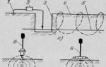
Atmospheric precipitation is removed from the roof of the building through. These are external lines of riser pipelines placed under the end points of the receiving gutters. In turn, receiving gutters are mounted along the perimeter of the roof area under the lower edge of the covering.


Collection of rain (melt) water from the roof area is carried out, first of all, by gutters. These structural elements are mounted along the lower edge of the roof covering and are adjacent to the riser at the lowest point of the slope. Next, the water is directed through the pipe to the rain receiver
On flat roofs, the drainage goes directly into the pipe risers. With this scheme, drain pipelines are usually mounted vertically inside buildings, and their upper sockets are brought out onto the roof and are integral with the roofing carpet. On flat roofs of private houses, the presence of one drainage funnel is permissible.
If the house uses internal risers with an open outlet, their design should provide for the possibility of draining melt water into the domestic sewage system in winter. The drain line must be equipped with a water seal. Based on the calculated data on the consumed mass of water, the diameter of the pipes for the construction of the storm sewer riser is selected.
Table for selecting pipes for the riser:
The preferred material for internal drain pipes is plastic, asbestos cement, cast iron. Tin and plastic pipes are usually used to construct an external storm drainage system.
When installing horizontal trunk lines, it is required to maintain a standard slope (not less than 0.005 m and not more than 0.15 m per 1 m of line length).


Storm drainage projects for private housing construction usually involve the use of plastic pipes for installation of linear highways. This is the most reliable option, but the most economical. However, frequent damage to individual areas negates all savings.
In case of maintenance, it is necessary to provide for the installation of inspections and cleanings. On storm sewer risers, audits are installed within the boundaries of the lower floor of the building.
In order to calculate the throughput of linear storm drainage trays, you need to take into account the area of the treated object, towards the channels and the water absorption coefficient adopted to cover the territory. In addition to these data, you will also need to calculate the hydraulic cross-section of the tray.
Image gallery


General principles for arranging a storm drain
Owners of private houses are quite capable of constructing communications for collecting and draining rain (melt) water with their own hands. After completing all the calculations and purchasing the required materials, they begin to arrange the storm drainage system.
First of all, they dig at local area trenches for drainage lines, according to the planned plan. Trenches are brought to the locations of drain risers (drainpipes). For planning a private household system, a trench depth of 300-500 mm is sufficient.

When excavating trenches, take into account the slope of future pipelines (or trays) towards the central storage reservoir. The bottom of the finished trenches is compacted by tamping and covered with a layer of river sand (at least 200 mm high)
On sites under drainpipes, pits are dug for storm water inlets and installed. These system elements are rectangular containers of small volume (5-10 liters).
To install inspection and rotary wells, it is recommended to use ready-made industrial ones or make them cast from polymer concrete. The first option is more expensive, but easier to install and maintain.
Industrially produced storm water inlets are usually supplemented with large waste collection baskets. Natural debris inevitably ends up in storm drains with rainwater flows.


One of the many existing storm drain designs. Manufacturing material – plastic. Optimal choice within private real estate projects. Such containers are usually supplemented with filter baskets to trap large debris
Based on the chosen technology for constructing storm sewers (open or closed), trays are laid in trenches or a line of
If you are making a simple tray drainage system with outlet to a nearby lawn, it is advisable to take into account the risks of possible soil erosion in the drainage areas. Elements of closed installation at joints must be sealed.
The communications collected in this way must be connected to a common storage tank or collector of a centralized network.
You should also take care of constructing sand filters immediately before entering the common storage tank. And don’t forget to install inspection wells. Their installation is necessary on sections of highways longer than 10 meters, as well as in places in the diagram where turns in the drainage line are formed.
Methods for discharging collected water
A serious challenge for owners countryside real estate is the drainage of rainwater collected from the total area of the site.
If there are no centralized communications near the house, there are two options left to solve this problem:
- Collection in a special tank and subsequent use for irrigation;
- Discharge of water from the reservoir into the ground or into natural areas.
The first option is considered rational, provided that there are watering facilities on the territory of the house. In this case, you will need a simple device (a household pumping station) to pump water from the storage tank and then supply it to the irrigation areas.


Scheme of drainage of collected rainwater into the ground. One of those possible schemes that are available to owners country houses. The efficiency in terms of removal speed is low, but given the use in small areas, this scheme is quite suitable
The second option is accompanied by great difficulties. Removal into the ground is a time-consuming process. How long it takes to hatch depends on the soil’s ability to absorb moisture. In different relief areas, the coefficient of soil saturation with moisture can differ significantly.
In order to divert the storm sewer product to natural areas (“to the relief” or “to the landscape”), an additional scheme will have to be implemented. This scheme includes a central reservoir and a groundwater treatment system, for example.
The “relief” or “landscape” output scheme is accompanied by difficulties in constructing treatment modules. Both options require approval from environmental authorities.
Typically, the owner of real estate (plot) has to contact the following organizations with the subject of approval:
- Department of Natural Surveillance.
- Fisheries Department.
- Office of Consumer Regulation.
- Basin and water management.
- CGMS.
The subject of approval means “Draft standards characterizing the discharge procedure.” Based on such a project, a permit is issued allowing the discharge of pollution “onto the landscape” or “on the relief”, and a decision is made on the provision of a water body.


Discharge of water from storm drains “to the relief” or “to the landscape”. Such schemes are not regulated in any way by SNiP documents.
Implementing such options illegally carries the risk of high fines, and legal disposal requires approval from the authorities.
Private real estate projects traditionally include other communication networks along with storm drainage. Domestic sewerage is also part of household communications. The principle of their operation differs little from the functioning of storm drains, in which owners of private houses often see the possibility of using these networks.
Meanwhile, the combination of storm sewerage with a domestic sewerage drainage system is prohibited by SNiP. Prohibition on combination different types sewerage is due to obvious factors.
Thus, provided that rainwater is discharged into the domestic sewer system and taking into account the high intensity of precipitation, the normal level of sewerage is increased several times.
Flooding of working wells leads to blockage of household and fecal wastewater. Mud deposits and natural debris flow into the domestic sewage system. As a result, after the next rainstorm, the organizers of the structure will have to clean the system.
Combining a storm drain with a sewer main threatens to result in disastrous results. Overflow of the drainage system due to violation of the design loads leads to flooding of the building foundation.
Frequent flooding disrupts the structure of the soil, which causes displacement of foundation blocks, erosion of the foundation under a monolithic structure, and in the future can lead to the destruction of the building.
Conclusions and useful video on the topic
Useful videos will expand your horizons about the purpose and installation of storm drains.
Video #1. Storm drainage in a private house - from design to installation:
Video #2. Industrial technologies:
The stages of design and careful calculation of storm drainage are an integral part of the construction of private houses. A carefully thought-out storm drain design and accurate calculations mean the durability of the structure and a comfortable environment for its inhabitants.
Would you like to tell us about how you installed a storm drain on your own summer cottage? Would you like to inform useful information and post a photo on the topic of the article? Please write comments in the block below.