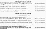
Conclusion based on the results of the building inspection. Our works and objects
List of software used by the company at the time of the survey
"1C: Enterprise 7.7" ("Accounting", "Trade", "Salary", "Personnel", "Cash", "Bank") for accounting work.
Two of our own developments based on the 1C configurator - “Purchases” and “Sales”.
Own development based on FOXPRO for the financial department.
Excel for sales planning.
Current level of automation
|
Number of workstations, total: | |
|
Number of IT department employees | |
|
Number of PCs simultaneously working on the network | |
|
Availability and form of communication with remote objects |
Terminal connection with the warehouse |
|
Number of workstations at a remote site | |
|
Computer Specifications |
From Celeron 600 and above |
|
Operating system | |
|
Systems that can be left unchanged |
"1C: Enterprise 7.7" in a modular composition "Accounting", "Salary", "Personnel", for accounting work |
General requirements for the information system
One of the main requirements of the MED company for the future solution is that it be built on the foundation of a single integrated system, and that all employees work in the same information space.
Key functional requirements for the information system:
Powerful means of protecting data from unauthorized access. Restrictions on access to data in accordance with job responsibilities.
Possibility of remote access.
Inventory Management. Prompt receipt of information about stock balances.
Procurement management. Planning of purchases by suppliers.
Sales management. Control of the debt limit with the ability to block the formation of shipping documents.
Full control of mutual settlements with suppliers and clients.
Receiving management reports in the necessary analytical sections - both detailed for managers and aggregated for department heads and directors of the company.
Examples of reporting document forms
|
Report on accounts receivable |
|||||||||||||||||||
|
Registration number |
Client |
Agreement |
Agreement date |
Amount according to the agreement |
Debt amount |
Expected payment term |
A comment |
||||||||||||
|
Report on accounts payable |
|||||||||||||||||||
|
Information about materials/components, services, work |
Provider |
№ agreement |
Amount according to the agreement |
Payment term according to the contract |
Date of payment |
Debt amount |
A comment |
||||||||||||
|
Report on required purchases |
||||||
|
Inventory code |
Name of material/product |
Unit |
measurements |
Required to purchase |
||
|
Previous date of purchase |
Supplier name |
Date of last purchase |
||||
Purchase cost
Description of the accounting system
CJSC "MED" uses a standard Russian chart of accounts, three analytics (counterparties, contracts, regions).
|
Fragment of the company's chart of accounts |
Account number accounts |
|
Account name |
|
|
Fixed assets |
|
|
Depreciation of fixed assets |
|
|
Profitable investments in material assets |
|
|
Intangible assets |
|
|
Amortization of intangible assets |
|
|
Investments in non-current assets |
|
|
Materials |
|
|
Raw materials |
|
|
Other materials |
|
|
Inventory and household supplies |
|
|
Reserves for reducing the cost of MC |
|
|
Deviation in the cost of MC |
|
VAT on purchases Fragment
accounting policy Revenue and profit
. Revenue from sales of products and provision of services is determined as sales of products sold and services are provided and is reflected in financial statements on an accrual basis. Reserves
. In order to determine the actual cost of goods sold in the reporting period, the company uses the option of valuing them at the cost of the first materials acquired in time (FIFO).
Description of reference books
|
A fragment of the description of directories used to automate the MED company is given in the table. |
Directory name |
||
|
Name |
|||
|
Buyer_PHARMACIES |
|||
|
Buyer_Distributors | |||
|
Suppliers/contractors |
|||
|
Private individuals |
|||
|
Insurance organizations | |||
|
Treaty |
1- our services |
||
|
Commission Agreement_D/M/G |
|||
|
Agreement for the provision of our services_D/M/Y | |||
|
2 - services to us |
|||
|
Agreement for the provision of services to us _D/M |
|||
Commission Agreement_D/M/G for services to us
The directory code reflects the hierarchy levels. Directories of clients and contracts have a three-level structure. Supplier Directory - two-level structure. In the reference code, the underscore character is used to display the level. For example, in the customer directory code, the first level is indicated by the symbols "AC" - buyer; second level - "Ar" - pharmacies, "Ds" - distributors; To designate the third level, five-digit serial numbers are provided: 00001, 00002, etc.
Organization chart
The organizational structure of the wholesale trade enterprise CJSC MED is as follows:
Description of the composition of automated business processes
Each business process has its own unique number. The numbering of business processes is based on the following principle: “prefix number”, where the prefix denotes the group of business processes being described, and the number is the serial number of the business process in the list.
MED company case diagram
The Use Case Diagram presents the company's automated business processes and their performers.

When performing work on the technical inspection of buildings, you should be guided by the “Safety Rules for Conducting Technical Inspections of Residential Buildings for the Design of Major Repairs” VSN 48-86 (r), as well as the relevant safety requirements when working with devices and tools.
When conducting a technical inspection of buildings during a general inspection, the following tasks must be performed:
assess the physical deterioration of structures and engineering systems, buildings in general;
check the condition of structures that have experienced various damages (leaks, floods, fire, etc.);
inspect structures that have undergone weakening of design sections during the redevelopment of buildings, floor additions, and deepening of the basement;
outline planned restoration measures (major and current repairs of the building);
identify possible measures for modernization or reconstruction of the building;
establish the causes of deformation of the load-bearing structures of the structure (walls, ceilings, columns);
establish the causes of dampness on the walls and freezing.
Based on the results of the survey, an inspection report, a conclusion or a report on the technical condition of the structures of a building or structure is drawn up, which provides information obtained from the design and executive documentation, and materials characterizing the operating features of structures that necessitate a separate survey. Approximate composition The technical inspection report is given in paragraph 4.6. VSN 57-88r:
- a list of documentary data on the basis of which the conclusion was drawn up;
- a brief technical description of the object indicating the purpose, number of storeys, main load-bearing structures, capital group and standard durability of the building;
- historiography of the structure;
- description of the location of the object;
- description of the general condition of the building based on external inspection;
- determination of physical and moral wear and tear of the building as a whole;
- description of building structures, their characteristics and condition;
- drawings of building structures with details and measurements;
- calculation of operating loads and verification calculations of load-bearing structures and foundations;
- measured plans and sections of the building, plans and sections of pits, wells, opening drawings;
- geological and hydrogeological conditions of the site, construction and permafrost characteristics of foundation soils (if necessary), operating conditions;
- analysis of the reasons for the emergency condition of the building, if any;
- photographs of facades and damaged structures;
- conclusions and recommendations.
List of documentary data, submitted by the customer, in the report can be combined in tabular form with brief technical description of the object.
The survey begins from the dominant point of the terrain - from load-bearing structures that are the first to meet seasonal snowfalls, storm drains and groundwater filtering in the same direction. The terrain of dense residential buildings is characterized as calm, pronounced and weakly expressed. When assessing the relief, it is necessary to note whether there is a tendency for surface runoff to stagnate for a long time on the site being surveyed, and how the structure itself is located in relation to the filtration paths of groundwater.
The main purpose of the visual technical inspection report is to provide an opinion on the technical condition of the object under study. Depending on the existing defects and damage, the technical condition of individual building structures can be classified into 4 categories according to the general characteristics given in Table. 5.
General assessment of the technical condition of load-bearing structures during a preliminary inspection of buildings
|
General signs characterizing the state of the structure |
|
|
I - normal |
There are no visible damages or cracks indicating a decrease in bearing capacity designs. Operating conditions are met in accordance with the requirements of standards and design documentation. There is no need for repair and restoration work. |
|
II - satisfactory |
The supporting structures have minor damage; in some areas there are individual shells, chips, gouges, and hairline cracks. The protective layers of the structures are partially damaged. Normal operating conditions are ensured. Current repairs are required, with the elimination of local damage without strengthening the structures. |
|
III - unsatisfactory |
There are damages, defects and cracks, indicating limited performance and a decrease in the load-bearing capacity of the structures. The requirements of current standards have been violated, but there is no danger of collapse or safety hazard. Strengthening and restoration of the bearing capacity of structures is required. |
|
Existing damage indicates the unsuitability of the structure for operation and the danger of its collapse, the danger of people staying in the area of the structures being inspected. Urgent measures are required to prevent accidents (installation of temporary support, unloading of structures, etc.). Required major renovation with strengthening or replacing damaged structures as a whole or individual elements. |
As can be seen from the table presented. 5, the condition of the structure as a whole depends on the condition of the main supporting structures. The greatest danger to the spatial rigidity of residential buildings comes from deformations and destruction in load-bearing structures and elements that have a large specific gravity in the mass of the structure itself: reinforced concrete, stone and reinforced stone, steel.
Assessment of the technical condition of the main load-bearing structures based on external features is based on the definition of:
geometric dimensions of structures and their sections;
condition of protective coatings (paint and varnish, plasters, protective screens, etc.);
deflections and deformations of structures.
Technical condition reinforced concrete load-bearing structures is assessed based on the following failure symptoms:
unacceptable deviations of compressible reinforced concrete elements from the vertical;
the presence of cracks, spalls and destruction;
deflections and deformations of bendable structures;
violation of the adhesion of reinforcement to concrete;
presence of reinforcement rupture;
anchorage conditions of longitudinal and transverse reinforcement;
degree of corrosion of concrete and reinforcement.
When determining geometric parameters reinforced concrete structures and their sections, all deviations from their design position are recorded. Reinforced concrete elements working in compression - according to the standards, can have a deviation from the vertical position of no more than 2 cm by 2 m.
During the inspection, it should be taken into account that the monolithic reinforced concrete frames of high-rise residential buildings that have been commissioned recently, as a rule, have deviations that exceed standard values by 7-8 times. The tilt of such buildings will only increase over time, since to speed up the process construction work, stripping of monolithic reinforced concrete structures is carried out until the concrete reaches 70% strength.
The picture shows a panorama of the collapse monolithic ceiling seventh floor during the construction of a multi-storey residential building in Belgorod on February 8, 2011. The ceiling between the sixth and seventh floors also failed, and the collapse did not develop below the sixth floor. In such cases, it is necessary to dismantle the entire frame of the structure, but in practice this does not happen.
Collapse of the monolithic ceiling of the seventh floor of a residential building under construction in Belgorod
Determining the width and depth of crack opening in reinforced concrete structures of operating residential buildings during a visual inspection is of decisive importance for ensuring the reliability of the structure as a whole. It is recommended to measure cracks primarily in places of their maximum opening and at the level of the tensile zone of the element.
The degree of crack opening is compared with the regulatory requirements for limit states of the second group, depending on the type and operating conditions of the structures. It is necessary to distinguish between cracks, the appearance of which is caused by stresses manifested in reinforced concrete structures during manufacturing, transportation and installation, and cracks caused by operational loads and environmental influences.
To the cracks that appeared in pre-operational period, include: technological, shrinkage cracks caused by rapid drying of the surface layer of concrete and reduction in volume, as well as cracks from concrete swelling;
cracks caused by uneven cooling of concrete;
cracks that appeared in prefabricated reinforced concrete elements during storage, transportation and installation, in which the structures were subjected to force effects from their own weight according to schemes not provided for by the design.
Cracks that appeared during operation include:
cracks resulting from thermal deformations due to violations of the requirements for the construction of expansion joints;
cracks caused by uneven settlement of the soil base, which may be associated with violation of the requirements for the construction of sedimentary expansion joints, excavation work in the immediate vicinity of the foundations without special measures;
cracks caused by force impacts exceeding the bearing capacity of reinforced concrete elements.
Force-type cracks must be analyzed from the point of view of the stress-strain state of the reinforced concrete structure.

Thanks to the timely evacuation of the residents of a monolithic building in the Turkish city of Diyabakir, no one was injured. Evacuation was carried out when cracks opened in a stretched zone of more than 0.5 mm, noticeable displacement of loggia supports, significant deflections of bending elements.
IN bendable reinforced concrete elements and structures operating according to the beam scheme(beams, purlins), cracks appear perpendicular to the (normal) longitudinal axis, due to the appearance of tensile stresses in the zone of action of maximum bending moments, and cracks inclined to the longitudinal axis, caused by the main tensile stresses in the zone of action of significant shear forces and bending moments.
Normal cracks have a maximum opening width in the outermost tensile fibers of the element's cross-section. Oblique cracks begin to open in the middle part of the side faces of the element - in the zone of maximum tangential stresses, and then develop towards the stretched face.
The formation of inclined cracks at the supporting ends of beams and girders indicates their insufficient load-bearing capacity along inclined sections. Vertical and inclined cracks in the spans of beams and girders indicate their insufficient bearing capacity in terms of bending moment.
The crushing of concrete in the compressed zone of sections of bending elements indicates the exhaustion of the bearing capacity of the structure;
IN reinforced concrete slabs The following cracks occur:
in the middle part of the slab, having a direction across the working span with maximum opening on the lower surface of the slab;
on supporting sections, directed across the working span with maximum opening on the upper surface of the slab;
radial and end, with possible loss of the protective layer and destruction of the concrete slab;
along the reinforcement along the lower plane of the wall.
Cracks in the supporting sections of the slabs across the working span indicate insufficient bearing capacity for bending support moment.
Assessment of the technical condition of reinforced concrete load-bearing structures based on preliminary survey data
 I – normal
On the surface of concrete of unprotected structures there are no visible defects or damage or there are small individual potholes, chips, hairline cracks (no more than 0.1 mm).
Anti-corrosion protection of structures and embedded parts has no violations.
When opened, the surface of the reinforcement is clean, there is no corrosion of the reinforcement, the depth of concrete neutralization does not exceed half the thickness of the protective layer.
The estimated strength of concrete is not lower than the design strength. The color of the concrete is not changed.
The amount of deflection and crack opening width do not exceed the permissible limits according to the standards.
 II – satisfactory condition of reinforced concrete structures
Anti-corrosion protection of reinforced concrete elements is partially damaged. In some areas, in places where the protective layer is small, traces of corrosion of distribution fittings or clamps appear, corrosion of working fittings in individual spots and spots; loss of cross-section of working reinforcement no more than 5%; There are no deep ulcers or rust plates.
Anti-corrosion protection of embedded parts was not detected. The depth of concrete neutralization does not exceed the thickness of the protective layer. The color of the concrete has changed due to overdrying, and in some places the protective layer of concrete has peeled off when tapped. Peeling of edges and edges of the structure
th, subjected to freezing.
The estimated strength of concrete within the protective layer below the design value is no more than 10%.
The requirements of current standards relating to limit states of group I are met; the requirements of the standards for limit states of group II may be partially violated, but normal operating conditions are ensured.
 III – unsatisfactory condition of reinforced concrete structures
Cracks in the tensile zone of concrete that exceed their permissible opening. Cracks in the compressed zone and in the zone of main tensile stresses, deflections of elements caused by operational impacts exceed the permissible limits by more than 30%. Concrete in the stretched zone at the depth of the protective layer between the reinforcement bars easily crumbles.
Lamellar rust or pitting on the rods of exposed working reinforcement in the area of longitudinal cracks or on embedded parts, causing a reduction in the cross-sectional area of the rods from 5 to 15%.
Reduction of the estimated strength of concrete in the compressed zone of bending elements to 30 and in other areas - to 20%.
Sagging of individual rods of distribution reinforcement, bulging of clamps, rupture of individual ones, with the exception of clamps of compressed truss elements due to steel corrosion (in the absence of cracks in this area).
The support area of prefabricated elements, reduced against the requirements of the standards and the design, with a drift coefficient K=1.6. High water and air permeability of wall panel joints.
 IV - pre-emergency or emergency
Cracks in structures experiencing alternating loads, cracks, including those crossing the support zone for anchoring tensile reinforcement; rupture of stirrups in the zone of an inclined crack in the middle spans of multi-span beams and slabs, as well as layered rust or pitting, causing a decrease in the cross-sectional area of the reinforcement by more than 15%; buckling of reinforcement in the compressed zone of structures; deformation of embedded and connecting elements; waste of anchors from plates of embedded parts due to corrosion of steel in welds, breakdown of joints of prefabricated elements with mutual displacement of the latter; displacement of supports; significant (more than 1/50 of the span) deflections of bending elements in the presence of cracks in the tension zone with an opening of more than 0.5 mm; rupture of clamps of compressed truss elements; rupture of clamps in the area of an inclined crack; rupture of individual rods of working reinforcement in the tension zone; crushing of concrete and crumbling of aggregate in a compressed zone.
Reduction in concrete strength in the compressed zone of bending elements and in other areas by more than 30%.
The support area of prefabricated elements is reduced against the requirements of the standards and the design. Existing cracks, deflections and other damage indicate the danger of destruction of structures and the possibility of their collapse
To classify a reinforced concrete structure into the listed condition categories, it is sufficient to have at least one feature characterizing this category.
Prestressed reinforced concrete structures with high-strength reinforcement, having signs of condition category II, belong to category III, and those having signs of category III, respectively, to category IV, depending on the danger of collapse.
If the support area of prefabricated elements is reduced against the requirements of the standards and the design, it is necessary to carry out an approximate calculation support element for shearing and crushing of concrete. The calculation takes into account the actual loads and strength of concrete.
In complex and critical cases, the assignment of the structure under examination to one or another condition category in the presence of signs not noted in the table should be made on the basis of an analysis of the stress-strain state of structures carried out by specialized organizations.
During inspection and assessment of technical condition stone and reinforced stone structures it is necessary to take into account the peculiarities of their operation and destruction caused by their structure.
 Diagonal cracks confined to openings in brick enclosing structures are the most dangerous confirmation of uneven sediments developing at the base.
Diagonal cracks in masonry with installed plaster beacon.
Masonry is a heterogeneous elastoplastic body consisting of stones and joints filled with mortar. This determines the following features of its operation: when masonry is compressed, the force is transferred unevenly due to local irregularities and unequal density of individual sections of the hardened mortar. As a result, the stones are subjected not only to compression, but also to bending and shearing.
The nature of the destruction of masonry and the degree of influence of numerous factors on its strength is explained by the peculiarities of its stress state during compression. Destruction of the usual brickwork during compression, it begins with the appearance of individual vertical cracks, as a rule, above and below vertical seams, which is explained by the phenomenon of bending and shearing of the stone, as well as the concentration of tensile stresses above these seams.
When examining stone and reinforced masonry structures, it is necessary first of all to identify load-bearing elements, the condition of which should be paid special attention to.
The first cracks in brickwork appear at loads less than destructive, and usually the ratio T= N crc/N u the less, the weaker the solution ( N crc— load corresponding to the moment of crack appearance,
So, for example, for masonry on mortar grades:
50 and above T= 0,7 — 0,8;
10 and 25 T= 0,6 — 0,7;
2 and 4 T= 0,4 — 0,6.
The moment the first cracks appear depends on the quality of the horizontal joints and the density of the mortar used.
In masonry made from large-sized products (high-hollow ceramic stones, stones made of cellular concrete), brittle failure occurs, the first cracks appear at loads of 0.85-1 from the breaking load.
An important reason that reduces the strength of masonry is the uneven density and shrinkage of the mortar. Partial filling of vertical joints with mortar does not lead to a decrease in the strength of the masonry, but reduces its crack resistance and solidity. Vertical seams and holes in hollow stones disrupt the solidity of the masonry and cause a concentration of tensile and shear stresses at the upper and lower ends of the cracks. Therefore, the strength of masonry made from hollow stones is reduced by 15-20% (with the exception of perforated bricks and ceramic stones with slot-like voids).
Assessment of the technical condition of stone structures based on external signs
|
Signs of structural condition |
|
|
I – normal
|
The structure has no visible deformations, damage or defects. The most stressed masonry elements do not have vertical cracks and bends, indicating overstress and loss of stability of the structures. There is no decrease in the strength of stone and mortar. The masonry is not moistened. Horizontal waterproofing is not damaged. The design meets the operational requirements. |
|
II - satisfactory
|
There are minor damages. Hairline cracks crossing no more than two rows of masonry (no more than 15 cm long). Defrosting and weathering of masonry, separation of cladding to a depth of up to 15% of the thickness. Load-bearing capacity is sufficient |
|
III – unsatisfactory
|
Average damage. Defrosting and weathering of masonry, peeling from the cladding to a depth of 25% of the thickness. Vertical and oblique cracks (regardless of the opening size) in several walls and pillars, crossing no more than two rows of masonry. Hairline cracks at the intersection of no more than four rows of masonry with the number of cracks no more than four per 1 m of the width (thickness) of the wall, pillar or pier. Formation of vertical cracks between longitudinal and transverse walls: ruptures or pulling out of individual steel connections and anchors securing walls to columns and ceilings. Local (edge) damage to the masonry to a depth of 2 cm under the supports of trusses, beams, purlins and lintels in the form of cracks and flanges, vertical cracks at the ends of the supports, crossing no more than two rows. The displacement of floor slabs on supports is no more than 1/5 of the embedment depth, but not more than 2 cm. In some places, dampening of the masonry is observed due to violation of the horizontal waterproofing, eaves overhangs, and drainpipes. Reducing the load-bearing capacity of masonry by up to 25%. Temporary reinforcement of load-bearing structures, installation of additional racks, stops, and couplers are required. |
|
IV - pre-emergency or emergency
|
Severe damage. Deformations, damage and defects are observed in structures, indicating a decrease in their load-bearing capacity by up to 50%, but not leading to collapse. Large collapses in the walls. Defrosting and weathering of masonry to a depth of 40% of the thickness. Vertical and oblique cracks (excluding temperature and sedimentation) in load-bearing walls and pillars at a height of 4 rows of masonry. Sloping and bulging of walls within a floor by 1/3 or more of their thickness. The opening width of cracks in the masonry due to uneven settlement of the building reaches 50 mm or more, the deviation from the vertical is more than 1/50 of the height of the structure. Displacement (shift) of walls, pillars, foundations along horizontal seams or oblique cuts. The design involves a reduction in the strength of stones and mortar by 30-50% or the use of low-strength materials. Separation of longitudinal walls from transverse ones at their intersections, ruptures or pulling out of steel ties and anchors securing walls to columns and ceilings. In brick vaults and arches, clearly visible characteristic cracks form, indicating their overstress and emergency condition. Damage to the masonry under the supports of beams and lintels in the form of cracks, crushing of stone or displacement of rows of masonry along horizontal joints to a depth of more than 20 mm. The displacement of floor slabs on supports is more than 1/5 of the embedment depth in the wall. |


If the horizontal waterproofing is damaged, the masonry in this area is easily disassembled using a crowbar, the stone crumbles, delaminates, and when you hit the stone with a hammer, the sound is dull.
In places of prolonged chronic soaking, freezing and weathering of masonry, local destruction of masonry occurs to a depth of 1/5 of the wall thickness or more. It is unacceptable for masonry to be separated vertically into separate independently working columns, or for walls to tilt or bulge within a floor by 1/3 of their thickness or more.
When masonry fails due to crushing in the supporting areas of beams and lintels, destruction of individual structures and parts of the building may occur. If deformations and defects are observed in structures, indicating a loss of their load-bearing capacity of more than 50%, there is a threat of collapse.
Until recently, the use of steel structures
. Metal structures have a low fire resistance limit and require fire and anti-corrosion protection, therefore it is assumed that they should be provided with open access for inspections during the entire period of operation. At the same time, metal is the main “cold bridge” in the structure, so its use was limited to unheated industrial buildings with technological regimes that involved a large release of heat.
 Recently, metal structures have been widely used for the construction of attic floors, not only in the superstructure of reconstructed buildings, but also in the construction of housing.
The photograph shows a residential building on the street. L. Tolstoy, Izhevsk. The apartments on the upper floor are made on two levels, the upper level is an attic floor with load-bearing metal structures. In the operational services of the city of Izhevsk, this house received the characteristic name “crying house”, because Residents have repeatedly called representatives of operating organizations and designers regarding unfavorable living conditions in the attic floor.
An inspection of the house showed that the roof did not leak, as the residents claimed. Condensed moisture was dripping from the ceiling, since the issues of thermal insulation of metal structures were not resolved during the design. Additional insulation of the attic floor from the inside led to an increase in corrosion damage to load-bearing structures. In addition, the designers did not properly organize the drainage from the roof. The walls of enclosing structures made of sand-lime brick are subject to constant waterlogging.
Analysis of survey data of operating attic floors in the Udmurt Republic, carried out by specialists of OJSC "UDMURTGRAZHDANPROEKT" on calls from residents living in them, allowed us to establish that the wetting of corners, ceilings and walls of attic floors is caused not by leaks, but by subsidence condensed water vapor. Moisture condensation occurs for the following reasons:
design flaws:
metal rafter structures come into contact with external and internal air, which causes the appearance of cold bridges;
the junctions between the walls and the covering have been decided incorrectly;
Incorrect or careless installation of thermal insulation;
Incorrectly performed thermal calculations, which is reflected in an insufficient layer of insulation and the use of ineffective insulation with a high percentage of hygroscopicity;
Lack of sufficient air gap between the roof covering and the insulation;
Lack of a vapor barrier layer at the bottom of the insulation or its damage during construction work;
Lack of through ventilation;
Absence of an anti-wind layer on top of the insulation.
In addition, residents of the lower floors complained about avalanche snowfall, and therefore, the survey results indicate that avalanche snowfall in winter is caused by:
Lack of thoughtful snow retention;
Lack of bypass bridges for clearing snow from the roof;
Insufficient roof slope.
|
|
|
|
Reconstruction of the hostel on the street. Avangardnaya in Izhevsk with the construction of an attic floor made of steel structures. The residents went to court twice because in winter the temperature in the attic floor was +5 0 C. During the reconstruction, the brickwork was wet and frozen.
|
|


During the inspection, roof leaks were also discovered, which were the result of the use of short-lived roofing material; non-compliance with roofing technology; incompetent solution of complex roof components (valleys; ridges; junctions with walls, riser outlets, ventilation shafts and ducts, installations of radio and television antennas). During the operation of the attic floor, the ventilation of the lower floors is disrupted, since the heads of the ventilation shafts are located in the aerodynamic shadow zone (especially with a complex roof structure) of the natural ventilation of the building.
The ineffectiveness of the external drainage system was revealed, which caused icing of the drainpipes and the formation of icicles during thaws.
Assessment of the technical condition of steel structures based on external signs
|
Signs of structural condition |
|
| I - normal | There are no signs characterizing wear of structures and damage to protective coatings |
| II - satisfactory | The anti-corrosion coating has been destroyed in places.
In some areas, corrosion in isolated spots affecting up to 5% of the section, local bends from vehicle impacts and other damage leading to a weakening of the section up to 5% |
| III - unsatisfactory | Deflections of bending elements exceed 1/150 of the span.
Lamellar rust with a reduction in the cross-sectional area of load-bearing elements by up to 15%. Local bends from vehicle impacts and other mechanical damage, leading to a weakening of the section by up to 15%. Curvature of truss gussets |
| IV - pre-emergency or emergency | Deflections of bending elements are more than 1/75 of the span. Loss of local stability of structures (buckling of walls and chords of beams and columns). Shearing of individual bolts or rivets in multi-bolt connections.
Corrosion with a reduction in the design cross-section of load-bearing elements to 25% or more Cracks in welds or in the heat-affected zone. Mechanical damage leading to a weakening of the section by up to 25%. Deviations of trusses from the vertical plane are more than 15 mm. Disruption of nodal connections due to turning bolts or rivets; ruptures of individual tensile elements; the presence of cracks in the base material of the elements; disorder of joints and mutual displacements of supports. Urgent measures are required to prevent accidents and collapse of structures |
At the stage of preliminary inspection of steel structures, recommendations are given on the need to take urgent measures to prevent the failure of structures classified as categories III and IV.
During a preliminary inspection of load-bearing metal structures, special attention should be paid to columns, frame crossbars, sub-rafters and trusses; purlins, nodes for supporting beams on ledges or consoles, joining joints of beams and their fastenings, for the safety of the protective layer of concrete of reinforced concrete structures in contact with metal embedded parts.
Based on the results of a visual inspection, a preliminary assessment of the technical condition is made building structures, which is determined by the degree of damage and characteristic signs of defects. A recorded picture of defects and damage (for example: in reinforced concrete and stone structures - the pattern of formation and development of cracks; in wood - places of biodamage; in metal - areas of corrosion damage) can make it possible to identify the causes of their origin and be sufficient for assessing the condition of structures and drawing up a conclusion.
If the results of a visual examination of load-bearing structures turn out to be insufficient to solve the assigned tasks, then a detailed instrumental examination is carried out. If signs indicating the occurrence of an emergency are identified, it is necessary to immediately develop recommendations to prevent a possible collapse. If defects and damage are detected that reduce the strength, stability and rigidity of the load-bearing structures of the structure (columns, beams, arches, floor and floor slabs, etc.), a detailed inspection work program is additionally developed.
If characteristic cracks, distortions of parts of the building, broken walls and other damage and deformations indicating the unsatisfactory condition of the soil foundation are detected, it is necessary to conduct an engineering-geological study, the results of which may require not only the restoration and repair of building structures, but also the strengthening of bases and foundations .
The standards do not stipulate the extent to which one or another item of the visual technical inspection report must be presented. As a rule, this is agreed with the customer and is dictated, first of all, by the purpose of the survey. To illustrate individual elements of the report, consider a fragment of reports on the technical inspection of a residential building.
Technical inspection report
residential building at the address Izhevsk, st. T. Baramzina, 48
Introduction
Technical inspection of a residential building at st. T. Baramzina, 48 was carried out on the basis of a letter of guarantee from the Rakurs HOA due to the need
- resumption of the system of regular technical inspections and compilation of a technical inspection log;
- restoration of the system of planned restoration measures with the issuance of recommendations on the composition of current and major repairs;
- drawing up a defective list of missed repair activities to justify statement of claim to the State Housing Administration of Izhevsk for reimbursement of the cost of repair work.
The customer was not provided technical documentation structures located in the State Housing Administration of Izhevsk. The construction is serial, privatized apartments have detailed technical inventory certificates, measuring drawings of the building are not required.
The survey was carried out in accordance with the requirements of VSN 57-88r “Regulations for the technical inspection of residential buildings.”

Historiography of the structure, location of the object
9-storey large-panel residential building of industrial development from the mid-70s. is located on the outskirts of a residential microdistrict, bounded by Tatyana Baramzina, Petrov, Truda streets, 150 m from the ravine.
The relief is pronounced, superficial and groundwater filtered in a northerly direction, towards the ravine. The building under examination is protected from the influence of the prevailing western and southwestern winds in Izhevsk by nearby houses.
The building inspected belongs to the first capital group “Especially capital”, with a standard durability of 150 years. The structure is made of large-block enclosing structures, the floors are hollow-core reinforced concrete, and the covering is rolled.
The surveyed object was put into operation in 1975. The building is in a period of normal operation. Judging by the external inspection, the structure was erected without visible signs of errors in design and construction.
The residential building inspected by now had to undergo 5 cycles of ongoing repairs with a mandatory increase in the moisture resistance of the facades, revision and repair of the joints of the fencing panels, cosmetic repairs of the entrances, and repair of the flat industrial coating.
In 2000, a complete overhaul was to be carried out, consisting of the following measures: replacement of all engineering communications, restoration of the blind area, replacement of all window and door fillings, strengthening of balconies and canopies with brick columns.
Instead, in 1997, the roof was repaired, in 2001, the internal water supply and sewerage systems were replaced, and poor-quality repairs were made to the collapsed blind area without installing a roller to drain water from the edge of the foundation.
In the summer of 2009, during ongoing repairs, the following was carried out:
— grouting cracks and painting the base;
— repair of stair railings, replacement of handrails;
— sealing cracks, painting the walls of the staircase;
- painting window frames;
- whitewashing of ceilings.
Thus, we can conclude that during the period of normal operation the structure is operated with significant deviations from regulatory requirements.
Description of the general condition of the building based on external inspection
The assessment of the condition of the structures of the building being examined was carried out according to VSN 53 “Rules for assessing the physical deterioration of residential buildings.”
The survey was carried out from the dominant point of the relief, along the path of surface runoff and groundwater filtration.


Considering the condition of the blind area, we can say with confidence that it does not cope with its purpose, therefore, the basement walls and foundations are subject to constant moisture.
Walls made of large-sized blocks.
When examining the external walls, attention was first paid to individual potholes in the textured layer.


Upon closer inspection, deviation of the upper end wall panels was noticed. In addition, weathering of the mortar in the joints was detected.
The surface layer of the fencing panels is riddled with horizontal “hairline” cracks.
At the ends of the structure, multiple delaminations of the mortar at the joints and cracks on the outer surface are visible. Inside the building, in the end apartments, traces of leaks in the premises are noticeable. Along the longitudinal facades there are cracks, potholes, peeling of the protective layer of concrete, leaks in places and freezing in the joints
Horizontal cracks are observed in the walls, vertical cracks in the lintels, bulging of concrete layers is noticeable, traces of leaks and freezing of panels
Crack width up to 3 mm. Buckling up to 1/200 of the distance between the supporting sections of the panels.


 |
 |
Partitions of load-bearing type. When examining the partitions, cracks up to 5 mm wide and crumbling of the mortar were found in places where they interfaced with window frames. In general, no destruction of the protective layer of the panels or cracks in the panels were detected. |
||
 |
Floors made of prefabricated slabs.During the construction of the building under study, hollow-core reinforced concrete floor slabs were used. In some rooms, cracks were found at the junctions with the walls. There are no cracks in the slabs themselves. |
|||
Reinforced concrete stairs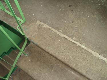 The building's staircases are made of reinforced concrete flights and platforms. The stair railings and railings are in good condition.
In some places, potholes and chips were found in the steps without exposed reinforcement.
Cracks between the flights of stairs and landings were repaired during the past repairs.
|
Protruding elements: balconies and loggias |
|
 |
When examining the loggias, attention is drawn to the local absence of a plaster layer and significant cracks in the walls with an opening width of up to 1 mm. There is minor damage to loggia fences, numerous shrinkage cracks, as well as damage to the floor and waterproofing. Upon inspection, pronounced corrosion of the metal parts of the balcony railings and significant chips in the slab were clearly noted. In addition, the outward slope of the balcony slab is clearly visible. The finishing layer of the fences is completely damaged. |
 |
 |
The roof is flat, industrial type, roll roofing
Due to the fact that the survey was carried out after the start of the heating season, no coverage was planned. However, the condition of the rolled carpet and the level of compliance with planned restoration measures by the operating organization can be judged by the condition of the ceiling of the 9th floor of the building, as well as by surveys of residents.
 |
 |
|
Traces of leaks in places where the coating slabs adjoin the external walls |
Traces of leaks in the area of the storm sewer |
Traces of leaks around the hatch
 |
 |
Based on this, we conclude that there is damage to the roofing carpet in places where it abuts vertical surfaces and small holes throughout the roof, and the insulation layer has become wet.
The roof railings are in satisfactory condition.
 |
 |
| Window blocks are wooden. When inspecting the windows, large cracks were found where the frames meet the walls. The window frames were cracked and warped. Rot damage and delamination of wood are noteworthy. |
The doors are wooden. The doors are in good condition. There is no damage. |
Oil painting.
Local isolated damage is visible in the paint layer.
The layout in all sections of the building being surveyed is convenient for family occupancy. The house is equipped with all types of amenities according to the standards (hot water supply, garbage chute, elevator, telephone connection), ceilings and partitions are non-flammable.
Technical conclusion
The condition of the building is assessed as satisfactory.
— restore inventory documentation;
— restore the technical inspection log with a technical inspection system.
foundations
— grouting cracks in the base;
— filling the seams between blocks;
— repair of plaster walls of the basement;
— repair of vertical and horizontal waterproofing and blind areas.
walls
— filling potholes, lining the textured layer;
- sealing seams.
load-bearing panel partitions
- sealing cracks and joints with window frames.
floors
— sealing cracks at the junctions of slabs and walls.
stairs
- sealing broken areas.
loggias
— repair of fences;
- grouting cracks;
balconies
- reinforcement of balconies with brick columns;
— repair of fences;
— replacement of waterproofing with installation of a cement floor.
roof
— roof repair in places;
— repair of water intake devices, cleaning of storm drains.
Window blocks
— complete replacement of window units.
Due to the fact that all damage is associated with violation of normal operation requirements, it is recommended that the cost of repair measures be presented to the organization that has been collecting housing and communal services from residents of the inspected structure for 34 years.
INTRODUCTION
This technical report was drawn up based on the results of measurements and examination of balconies located on the front facade of a residential apartment building at the address: St. Petersburg, st. xxxxxxxxxxx, d.x, letter x.
Survey objectives— expert assessment of the actual technical condition of the balconies of the front and courtyard facades.
Purpose of the survey— determining the suitability of structures for further trouble-free operation with issuing recommendations on the nature and scope of upcoming repair and restoration work.
In accordance with the Terms of Reference, the work program for this survey included the following activities:
- Obtaining and analyzing initial data;
- Detailed inspection of structures with sketches, measurements and photographs of defects and damage identified by external signs;
- Study of the design features of balconies;
- Determination of types and compositions of floors;
- Measurement work;
- Analysis of identified defects and damages;
- Determination of the degree of physical wear of structures;
- Drawing up a conclusion with conclusions and recommendations for further operation of structures.
The survey work, processing of the results, preparation of the conclusion and execution of this report were carried out in accordance with the following regulatory and guidance documents:
- GOST R 53778-2010 “Buildings and structures. Rules for inspection and monitoring of technical condition";
- SP 13-102-2003 “Rules for inspection of load-bearing building structures of buildings and structures”;
- VSN 53-86(r) “Rules for assessing the physical deterioration of residential buildings.”
As initial data, the materials of the Technical Data Sheet compiled by the State Unitary Enterprise “GUION” PIB of the Kirov region as of 04/18/2012 were used.
For quantification technical condition of the examined structures, a detailed scale was used to characterize the degree of physical wear, correlating with the categories of condition according to GOST R 53778-2010 and SP 13-102-2003.
1. SUBJECT OF INVESTIGATION
1.1. Brief description of the building
The building in question is a five-story residential building (apartment residential building) with a basement and an unused cold attic, having a rectangular plan with overall dimensions of 101.52 x 11.32 m.
The year of construction and commissioning of the building was 1940.
Capital group – I.
The height of the building (cornice mark) is 20.35 m from the ground surface level. The height of the basement premises (technical underground) is 2.6 m. The average height of the internal premises of the above-ground floors is 3.25 m.
According to the structural design, the building is frameless, with longitudinal and transverse load-bearing walls. The spatial rigidity of the load-bearing frame is ensured by the joint work of the walls, the hard disks of the interfloor floors, as well as the walls of the staircases.
Constructive decisions:
| – Foundations: | rubble tape; |
| - Walls: | brick 510-640 mm thick; |
| – Partitions: | plaster, wooden; |
| – Floors: | prefabricated reinforced concrete slabs; |
| - Roof: | pitched, on a wooden rafter system; |
| – Roof: | made of galvanized steel over wooden sheathing; |
| – Floors: | planks, parquet, ceramic tiles; |
| – Stairs: | prefabricated reinforced concrete marches; |
| – Windows/doors: | double casement / paneled; |
| – Balconies: | reinforced concrete slab on cantilever beams embedded in the walls; |
| – Finish: | front facade - concrete facing slabs, courtyard facade - smooth plaster. |
The building is served by five staircases, accessed from the courtyard façade.
The building is equipped with all types of engineering equipment: central heating, cold and hot water supply, sewerage, gas and electricity supply.
Technical and economic indicators:
1.2. Layout and design of the surveyed balconies
The balconies of the 3rd and 4th floors of residential apartments Nos. 15-18, 25-28, 35-38, located on the front facade of the building in question, were subject to inspection. The total number of surveyed balconies is 12 pcs.
The location and marking diagram of the surveyed balconies is shown below in Fig. 1. A fragment of the front façade of the building indicating the marked balconies is presented in Fig. 2.
It should be noted that all information accumulated during the survey (including conclusions based on the survey results) will be presented in relation to the diagram below.
FIGURE 1. Layout of the surveyed balconies (fragment of the façade)
 FIGURE 2. Fragment of the facade showing marked balconies

FIGURE 3. Basic design of the balconies being examined
2. SURVEY RESULTS
The inspection of the balconies was carried out through a detailed inspection of the structures from the apartments and from the street side with photographic recording of defects identified by external signs. The survey results are summarized in Table 3. Photo recording materials are presented in Appendix 1.
TABLE 3. Visual examination results
|
No. |
Characteristics of the defect |
Defect detected |
| Structural defects in the connection between the balcony floor and the door frame of the balcony door: the cement floor is made flush with the top of the concrete balcony step; insufficient threshold height (2-3 cm); |
in all apartments except apt. 26 |
|
| The slope of the floors does not ensure normal drainage of water to the drain hole, as evidenced by the presence of areas of stagnant water (puddles) and traces of dampness along the internal contour of the balconies |
in apartments No. 15,16,27, 28,38 |
|
| Vertical crack in a baluster with an opening of 2-3 mm |
in apartments No. 15,16 |
|
| Cluttering of the balcony, preventing the normal drainage of water to the drain hole |
in apartments No. 25,26 |
|
| Destruction of the protective plaster layer along the edge of the supporting string under the balusters due to prolonged soaking |
in apartment No. 27 |
|
| A deep crack in the supporting pedestal of the balcony fencing, extending into the supporting string of the balusters, with an opening of more than 1 cm |
in apartment No. 38 |
|
| Lack of galvanized metal apron on the handrails of the fence |
in apartment No. 28 |
|
| Defects in the external finishing coating of balconies: traces of leaks (dull and damp spots), darkening and contamination of the paint layer; peeling, shedding and destruction of the plaster layer in places. |
in all apartments |
Based on the results of an examination of balconies located on the front facade of a residential apartment building at the address: St. Petersburg, st. xxxxxxxx, d.x, letter A, the following conclusions can be drawn:
1. The general technical condition of the balconies is assessed as limited performance. Physical wear and tear, in accordance with Table 37 VSN 53-86(r), is 30-36%.
2. The limitation in the operability of balconies is due, first of all, to design errors and shortcomings made during the repair of balconies (in all apartments except apartment 26), namely:
- Incorrect solution for the junction of the balcony floor and the door frame of the balcony door: the existing cement floor is made flush with the top of the concrete step of the balconies, and the height of the threshold is only 2-3 cm. The result of this is leaks along the sealing line of the balcony slabs (rain and melt water, which is especially noticeable in the winter season);
- The slope of the existing floors does not ensure normal drainage of water to the drain holes, as a result of which the structures and finishing coverings of balconies are operated for a long time in a constant soaking mode, which negatively affects their strength and durability.
3. A number of operational defects have also been identified, the appearance of which is due to many years of soaking of structures due to faulty waterproofing and the lack of timely preventive repairs: cracks, absence or unsatisfactory condition of metal aprons, defects and damage to exterior finishing.
To restore the operational suitability of balconies, repairs are necessary (without increasing the load-bearing capacity), during which it is necessary to provide for the following measures:
- In all apartments inspected (except for apartment No. 26), dismantle the existing cement floor of the balconies, followed by installation of a new floor and waterproofing with high-quality compaction and sealing of all seams and interface areas, creating slopes (2-3%) to ensure normal drainage of water to the drains holes. The recommended design of the interface between the balcony floor and the door frame of the balcony door is shown below in Fig. 4.
- Repair cracks in the balusters of the balcony railing of apartments No. 15, 16 by sealing with a polymer cement mortar prepared from a dry cement-sand mixture M150, mixed with a 10% aqueous solution of stabilized latex SKS-65gp grade B in the ratio “1 part latex”: “ 4 parts water" (it is forbidden to use PVA dispersion instead of latex).
- Repair a crack in the support pedestal and the bowstring of the balcony railing in apartment No. 38. Carry out work by analogy with clause 4.2.
- Restore the missing metal apron of the handrail-parapet of the balcony railing in apartment No. 28.
- Repair external finishing coatings all balconies.
- It is also recommended to prohibit residents from placing heavy and massive objects on their balconies after repairs that would prevent the flow of atmospheric water to the drain holes.
 FIGURE 4. Interface unit between the balcony floor and the balcony door frame
1 – balcony slab or external wall; 2 – interfloor slabs;
3 – concrete balcony step (existing); 4 – insulation; 5 – door frame (shown conditionally); 6 – wooden lining bars (shown conditionally); 7 – brickwork; 8 – concrete preparation; 9 – board (shown conditionally).
Appendix 1. Photo recording materials
PHOTO No. 1. Balcony of apartment No. 15 (3rd floor)
— Structural defects in the design of the interface between the balcony floor and the door frame of the balcony door: the cement floor is made flush with the top of the concrete balcony step; insufficient threshold height (2-3 cm);
— The slope of the floor does not ensure normal drainage of water to the drain hole, as evidenced by traces of dampness along the internal contour of the balcony.
PHOTO No. 2. Balcony of apartment No. 16 (3rd floor)
— Vertical crack in the baluster with an opening of 2 mm;
— Insufficient height of the balcony threshold, which allows moisture to penetrate into the apartment.
PHOTO No. 3. Balcony of apartment No. 27 (4th floor)
— Destruction of the protective finishing layer along the edge of the supporting string under the balusters due to prolonged soaking;
— The slope of the balcony floor does not ensure normal water drainage to the drain hole, as evidenced by stagnation of water on the balcony.
PHOTO No. 4. Balcony of apartment No. 38 (4th floor)
— A deep crack in the supporting pedestal of the balcony fence, turning into the supporting string of balusters, with an opening of more than 1 cm.
PHOTO No. 5. General view of the balcony of apartment No. 37 (4th floor)
— Darkening and contamination of the paint layer.
— Traces of intense leaks, peeling, crumbling and destruction of the plaster layer in places.
Buildings of section No. 1.
The right to carry out this type of work is confirmed by the Certificate of Admission.
The inspection was caused by the need to assess the technical condition of the building structures in connection with the existing deformations of the structural elements.
IN project documentation The survey of building structures included the following types of work:
- carrying out measurement work to determine the parameters of the load-bearing structural elements of the building;
- assessment of the actual technical condition of the main load-bearing structures and the building as a whole;
- issuing recommendations to ensure the further operational suitability of the building.
Based on the results of a survey carried out in accordance with the requirements
SP 13-102-2003 and GOST 53778-2010, this report has been compiled, including:
- drawings of the building (plans, sections, facades);
- results of inspection of structures (walls, floors, coverings, structural elements) with photographic recording of existing defects;
- conclusions on assessing the technical condition of structures;
- recommendations for ensuring further normal operation of the building.
The following documentation was used when performing the work:
1. Technical passport for the warehouse building.
2. Fragment of topographic survey of the building site.
2.2. Brief description of the object
2.2.1. Total information
The building under examination is located in Rostov-on-Don.
Climatic conditions:
- Climatic region - III B;
- estimated winter temperature - 220 C;
- calculated snow load for snow region II (according to SNiP 2.01.07-85*) on the horizontal projection of the roof - 1.20 kPa;
- standard wind speed for region III (according to SNiP 2.01.07-85*) at an altitude of up to 10 m - 0.38 kPa;
- standard soil freezing depth (according to SNiP 2.02.01-83) - 0.9 m;
- seismicity of the area - 6 points.
Building characteristics:
- the level of responsibility of the building is normal;
- degree of durability - II;
- degree of fire resistance of the building - II;
- functional fire hazard class - f 1.1.
Technical and economic indicators:
Total area - 687.8 m2.
Construction volume - 2313 m3.
2.2.2. Conditions of construction and operation of the building
The warehouse building was built in 1966. There is no information about previous inspections of the building, as well as about surviving documentation for the construction of the building.
According to the employees operating the building, several years ago, for a long time, the foundation soils were soaked with hot water supply water (in the area of axis “2”).
During the survey, it was noted that part of the building in axes “1”-“2” was added later than the main building.
In close proximity to axis “5” of the building being examined, the neighboring one is located.
During the inspection of the building, increased humidity and dampness were noted in the basement areas.
2.2.3. Space planning and design solutions
The building is one-story brick, rectangular in plan, with total dimensions in axes 37.3x11.7 m. Under part of the building in axes “2/1”-“4” there is a basement with a height of 2.4 m. The height of the first floor is 3.7… 3.8 m.
The structural design of the building is frameless with load-bearing brick longitudinal walls.
The foundations are strip foundations on a natural foundation.
The basement ceiling is reinforced concrete hollow-core slabs.
The covering is reinforced concrete ribbed and hollow-core slabs.
The beam on which the floor slabs rest in axes “1” - “2” is metal.
The lintels over the window openings are metal.
The roof is made of rolled fused materials.
Plans, sections and facades are shown on sheets of the graphic part and in photographs in Appendix 4.1.
2.3. Structural Inspection
2.3.1. Foundations and engineering-geological conditions
During the inspection of the building, the foundations were not opened or studied.
There are no data on engineering-geological surveys. The terrain of the area is calm and flat.
 2.3.2. Walls and lintels
Wall and lintel materials
The walls of the building are made of ceramic bricks. The surface of the walls in the premises is plastered. The thickness of the external and internal walls is 440 mm with a plaster layer. Brick brand M100.
In the basement and first floor rooms, partitions with a thickness of 150...300 mm made of brick are installed.The thickness of the building walls does not meet the requirements of heating engineering standards.
Defects in walls and lintels
The main defects in the walls of the building are vertical, inclined and horizontal cracks of a sedimentary nature. The opening width of cracks in the walls of a building is up to 15 mm. Maximum deformations are marked in axes “1” - “3”.
The lintels over the building openings are made of metal from an angle L75x75 and a channel)